SECTION 5: SHOP MADE SAFETY ACCESSORIES
Featherboards
Easily made from scrap stock, featherboards provide an added degree of protection against kickback, especially when used together with push sticks. They also maintain pressure on the workpiece to keep it against the fence or table while cutting, which makes the operation easier and safer because the cut can be completed without the operator's hands getting near the blade. The angled ends and flexibility of the fingers allow the workpiece to move in only one direction.
Making a Featherboard
This sub-section covers the two basic types of featherboards: 1) Those secured by clamps, or 2) those secured with the miter slot.
Material Needed for Featherboard Hardwood 3/4" x 3" x 10" (Minimum)
- Hardwood 3/4" x 6" x 28" (Maximum) ........ 1
Additional Material Needed for Mounting Featherboard in Miter Slot
- Hardwood 3/8" x (Miter Slot Width) x 5"L ........ 1
- Wing Nut 1/4"-20 ........ 1
- Flat Head Screw 1/4"-20 x 2" ........ 1
- Flat Washer 1/4"-20 ........ 1
To make a featherboard:
-
Cut a hardwood board approximately 3/4" thick to size. The length and width of the board can vary according to your design. Most featherboards are 10"–28" long and 3"–6" wide. Make sure the wood grain runs parallel with the length of the featherboard, so the fingers you will create in Step 3 will bend without breaking.
-
Cut a 30° angle at one end of the board.
! CAUTION We recommend using a bandsaw for making fingers in the next step because it tends to be safer. A table saw can be used, but it will over-cut the underside of the ends, produce a thicker kerf, and require you to stop the blade half-way through the cut, which can be dangerous.
- Make a series of end cuts with the grain 3/8"–1/4" apart and 2"–3" long, as shown in Figure 71 (A). Alternatively, start cuts at 2"-3" deep, then make them progressively deeper, as shown in Figure 71 (B).
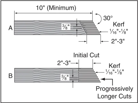
Figure 71. Patterns for featherboards (top view shown).
IMPORTANT: Cuts made across the grain result in weak fingers that easily break when flexed. When made correctly, the fingers should withstand flexing from moderate pressure. To test the finger flexibility, push firmly on the ends with your thumb. If the fingers do not flex, they are likely too thick (the cuts are too far apart).
NOTICE Only Steps 1–3 are required to make a clamp-mounted featherboard. Refer to Page 52 for instructions on clamping.
-50- Model G0690/G0691 (Mfd. 6/15+)

- Rout a 1/4"–3/8" wide slot 4"–5" long in the workpiece and 1"–2" from the short end of the featherboard (see Figure 72).
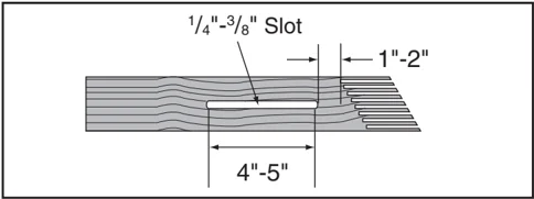
Figure 72. Slot routed in featherboard.
- Cut a miter bar that will fit in the table miter slot approximately 5" long, as shown in Figure 73.
Tip: Consider making the miter bar longer for larger featherboards—approximately half the length of the total featherboard—to support the force applied to the featherboard during use.
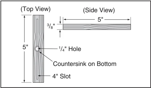
Figure 73. Miter bar pattern.
-
Drill a 1/4" hole in the center of the bar, then countersink the bottom to fit a 1/4"-20 flat head screw.
-
Mark a 4" line through the center of the countersunk hole in the center, then use a jig saw with a narrow blade to cut it out.
-
Assemble the miter bar and featherboard with a 1/4"-20 x flat head screw, flat washer, and a wing nut or a star knob (see Figure 74). Congratulations! Your featherboard is complete.
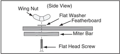
Figure 74. Assembling miter slot featherboard components.
Note: The routed slot, countersink hole, and the flat head screw are essential for the miter bar to clamp into the miter slot. When the wing nut is tightened, it will draw the flat head screw upward into the countersunk hole. This will spread the sides of the miter bar and force them into the walls of the miter slot, locking the featherboard in place.
Tip: The length of the flat head screw depends on the thickness of the featherboard—though 1-1/2" to 2" lengths usually work.
Now, proceed to Mounting Featherboard in Miter Slot on Page 52.
Mounting Featherboards w/Clamps
- Lower the saw blade, then adjust the fence to the desired width and secure it.
- Place the workpiece against the fence, making sure it is 1" in front of the blade.
- Place a featherboard on the table away from the blade so all fingers point forward and contact the workpiece (see Figure 75).
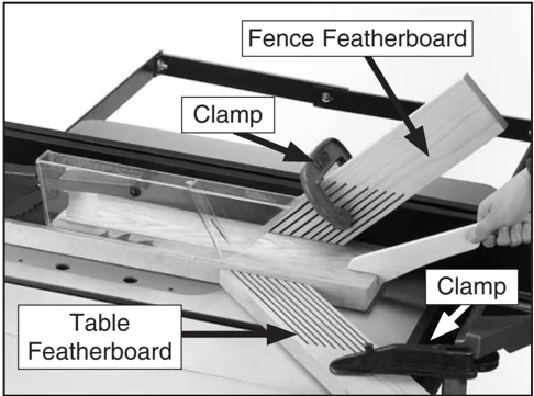
Figure 75. Example of featherboards secured with clamps.
- Secure the featherboard to the table with a clamp.
- Check the featherboard by pushing it with your thumb to ensure it is secure. —If the featherboard moves, tighten the clamp more.
- Mount a second featherboard to the fence with another clamp (see Figure 75), then repeat Step 5 to ensure it is secure.
Mounting Featherboard in Miter Slot
- Lower the saw blade, then adjust the fence to the desired width and secure it.
- Place the workpiece evenly against the fence, making sure it is 1" in front of the blade.
- Slide the featherboard miter bar into the miter slot, making sure the fingers slant toward the blade, as shown in Figure 76.
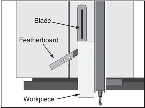
Figure 76. Featherboard installed in miter slot and supporting workpiece for ripping cut.
- Position the fingered edge of the featherboard against the edge of the workpiece, so that all of the fingers contact the workpiece. Slide the featherboard toward the blade until the first finger is nearly even with the end of the workpiece, which should be 1" away from the blade.
- Double check the workpiece and the featherboard to ensure they are properly positioned as described in Step 4. Then secure the featherboard to the table. Check the featherboard by hand to make sure it is tight.
Note: The featherboard should be placed firmly enough against the workpiece to keep it against the fence but not so tight that it is difficult to feed the workpiece.
Push Sticks
When used correctly, push sticks reduce the risk of injury by keeping hands away from the blade while cutting. In the event of an accident, a push stick can also absorb damage that would have otherwise happened to hands or fingers.
Using a Push Stick
Use push sticks whenever your hands will get within 12" of the blade. To maintain control when cutting large workpieces, start the cut by feeding with your hands then use push sticks to finish the cut, so your hands are not on the end of the workpiece as it passes through the blade.
Feeding: Place the notched end of the push stick against the end of the workpiece (see inset Figure below), and move the workpiece into the blade with steady downward and forward pressure.
Supporting
A second push stick can be used to keep the workpiece firmly against the fence while cutting. When using a push stick in this manner, only apply pressure before the blade; otherwise, pushing the workpiece against or behind the blade will increase the risk of kickback (see "Push Stick Prohibition Zone" in the Figure below).
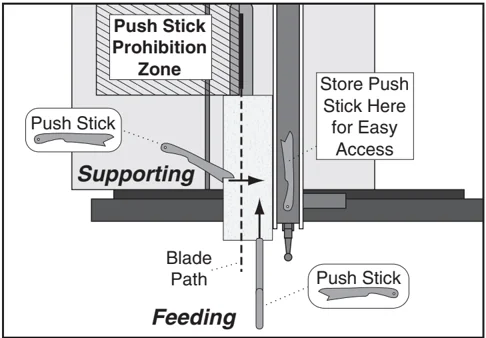
Figure 77. Using push sticks to rip narrow stock.
Making a Push Stick
Use this template to make your own push stick.
Figure 78. Side view of a push stick in-use.
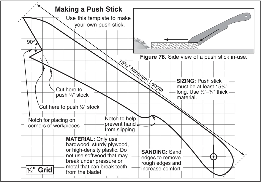
Figure 79. Template for a basic shop-made push stick (not shown at actual size).
SIZING: Push stick must be at least 15-3/4" long. Use 1/2"–3/4" thick material.
MATERIAL: Only use hardwood, sturdy plywood, or high-density plastic. Do not use softwood that may break under pressure or metal that can break teeth from the blade!
SANDING: Sand edges to remove rough edges and increase comfort.
Model G0690/G0691 (Mfd. 6/15+) -53-
Push Blocks
When used correctly, a push block reduces the risk of injury by keeping hands away from the blade while cutting. In the event of an accident, a push block often takes the damage that would have otherwise happened to hands or fingers.
Using a Push Block
A push block can be used in place of or in addition to a push stick for feeding workpieces into the blade. Due to their design, push blocks allow the operator to apply firm downward pressure on the workpiece that could not otherwise be achieved with a push stick.
The push block design on this page can be used in two different ways (see inset Figure below). Typically, the bottom of the push block is used until the end of the workpiece reaches the blade.
The notched end of the push block is then used to push the workpiece the rest of the way through the cut, keeping the operator's hands at a safe distance from the blade. A push stick is often used at the same time in the other hand to support the workpiece during the cut (see "Using a Push Stick" on previous page).
 Figure 81. Using a push block and push stick to make a rip cut.
Making a Push Block
Use this template to make your own push block.
 Figure 80. Side view of a push block in use.
Figure 82. Template for a shop-made push block (shown at 50% of full size).
Narrow-Rip Auxiliary Fence & Push Block
There are designs for hundreds of specialty jigs that can be found in books, trade magazines, and on the internet. These types of jigs can greatly improve the safety and consistency of cuts. They are particularly useful during production runs when dozens or hundreds of the same type of cut need to be made.
The narrow-rip auxiliary fence and push block system shown in this section is an example of a specialty jig that can be made to increase the safety of very narrow rip cuts.
Material Needed for Narrow Rip Auxiliary Fence & Push Block
- Hardwood 3/4" x 3" x Length of Fence ........ 1
- Plywood 3/4" x 5-1/4" x Length of Fence ........ 1
- Wood Screws #8 x 1-1/2" ........ 8
Material Needed for Push Block
- Hardwood or Plywood 3/4" x 15" x 5-5/8" ........ 1
- Hardwood or Plywood 3/4" x 10" x 5"-9" ........ 1
- Cyanoacrylate Wood Glue ........ Varies
- Wood Screws #8 x 1-1/2" ........ As Needed
Making a Narrow-Rip Push Block for an Auxiliary Fence
- Cut a piece of 3/4" thick plywood 5-1/4" wide and as long as your table saw fence; cut a piece of 3/4" thick hardwood 3" wide and as long as your table saw fence, as shown in Figure 83.
 Figure 83. Auxiliary fence dimensions.
Note: We recommend cutting the hardwood board oversize, then jointing and planing it to the correct size to make sure the board is square and flat. Only use furniture-grade plywood or kiln dried hardwood to prevent warping.
- Pre-drill and countersink eight pilot holes 3/8" from the bottom of the 3" wide board, then secure the boards together with eight #8 x 1-1/2" wood screws, as shown in Figure 84.
 Figure 84. Location of pilot holes.
- Using the 3/4" material you used in the previous steps, cut out pieces for the push block per the dimensions shown in Figure 85; for the handle, cut a piece 10" long by 5"-9" high and shape it as desired to fit your hand.
 Figure 85. Push block dimensions and construction.
- Attach the handle to the base with #8 x 1-1/2" wood screws, and attach the lip to the base with cyanoacrylate type wood glue.
Model G0690/G0691 (Mfd. 6/15+) -55-
Using the Auxiliary Fence and Push Block
- Place the auxiliary fence on the table and clamp it to the fence at both ends, then adjust the distance between the auxiliary fence and the blade—this determines how wide the workpiece will be ripped (see Figure 86).
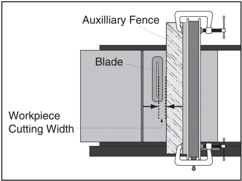
Figure 86. Adjusting ripping distance between blade and auxiliary fence.
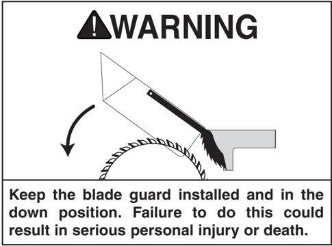
- Install the blade guard, then secure the spreader pawls in the upright position, as shown in Figure 51 on Page 38, so they do not interfere with the push block lip.
- Place the workpiece 1" behind the blade and evenly against the table and the auxiliary fence.
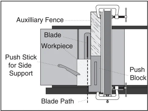
Figure 87. Push block in position to push workpiece through blade.
-
Turn the saw ON, then begin ripping the workpiece using a push stick for side support.
-
As the workpiece nears the end of the cut, place the push block on the auxiliary fence with the lip directly behind the workpiece, then release the push stick just before the blade.
-
Guide the workpiece the rest of the way through the cut with the push block, as shown in Figure 88.
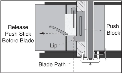
Figure 88. Ripping with push block.
!(WARNING) Turn OFF the saw and allow the blade to come to a complete stop before removing the cut-off piece. Failure to follow this warning could result in serious personal injury.
Outfeed & Support Tables
One of the best accessories for improving the safety and ease of using a table saw is simply placing a large table (outfeed table) behind the saw to catch the workpiece (see Figure 89). Additionally, another table to the left of the saw (support table) can also help support large workpieces so they can be cut safely and accurately.
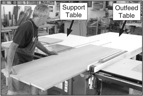
Support Table
Outfeed Table
Figure 89. Example of outfeed & support tables.
Crosscut Sled
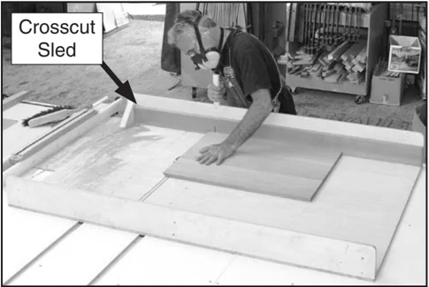
A crosscut sled (see Figure 90) is a fantastic way to improve the safety and accuracy of cross-cutting on the table saw. Most expert table saw operators use a crosscut sled when they have to crosscut a large volume of work, because the sled offers substantial protection against kickback when crosscutting.
Crosscut Sled
Figure 90. Example of crosscut sled.
Model G0690/G0691 (Mfd. 6/15+) -57-
SECTION 6: ACCESSORIES
WARNING
Installing unapproved accessories may cause machine to malfunction, resulting in serious personal injury or machine damage. To reduce this risk, only install accessories recommended for this machine by Grizzly.
NOTICE
Refer to our website or latest catalog for additional recommended accessories.
H7583—Grizzly Tenoning Jig
Our fully adjustable tenoning jig handles stock up to 3-1/4" thick and features an adjustable bevel angle with a 90° to 75° range. The two large grip handles, adjustable guide bar, multi-position control levers, and extra large clamping handwheel will ensure accurate and repeatable results. A top seller!
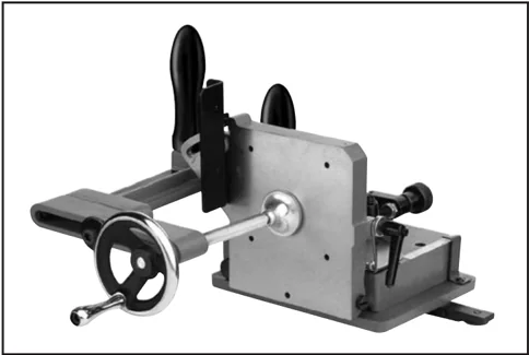
Figure 91. Model H7583 Tenoning Jig.
D2057A—Heavy-Duty Mobile Base
This patented base is the most stable on the market with outrigger type supports. Adjusts from 20" x 20" to 29-1/2" x 29-1/2". 700 lb. capacity. Weighs 34 lbs.
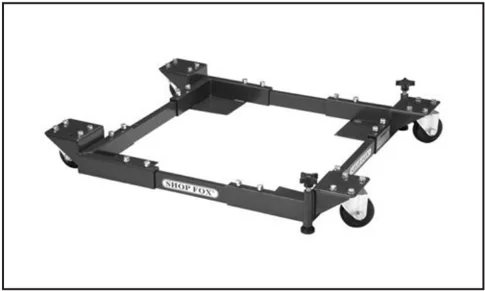
Figure 92. Model D2057A Mobile Base.
D2259A—Extension Kit for D2057A
This kit easily bolts onto Model D2057A to provide support for an extension table or similar device. Allows the whole machine and extension to move as one unit. Adjustable length up to 45-3/4", and legs can be adjusted front to back. Very versatile!
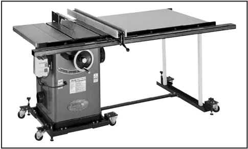
Figure 93. Model D2259A Extension Kit.
order online at www.grizzly.com or call 1-800-523-4777
T10222—Router Table Attachment
T10223—Sliding Table Attachment
Accessorize your G0690 or G0691 Cabinet Table Saw with either of these attachments for the ultimate in table saw functionality.
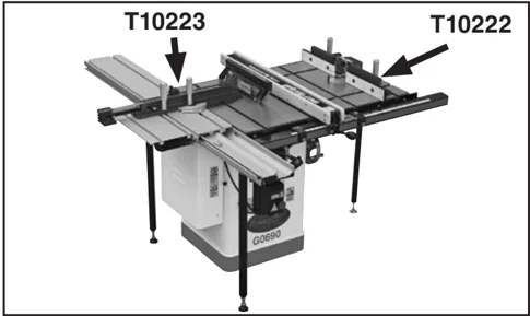
Figure 94. T10222-23 Sliding Table & Router Table Attachments.
Forrest Woodworker II Saw Blades
- T20778—10", 20 Teeth
- T20779—10", 40 Teeth
- T23527—10", 48 Teeth
Hailed as the Cadillac of all blades, Forrest saw blades have become legendary for their ability to leave highly polished, finish-ready surfaces on nearly everything they cut. Made in the USA.
With this all-purpose blade for table saws you can rip and crosscut 1" 2" rockhards and softwoods, resulting in a smooth-as-sanded surface. With 20° face hook, ply veneers will crosscut with no bottom splinter at moderate feed rates. Double hard and 40% stronger C4 carbide will give up to 300% longer life between sharpenings. Ends blade changing (one blade does rip, combo and crosscut), second-step finishing and cutting 1/16" oversize to allow for resurfacing. Buy and sharpen one blade instead of 3 (24T rip, 50T combination and 80T crosscut). 5/8" arbor, 1/8" kerf.
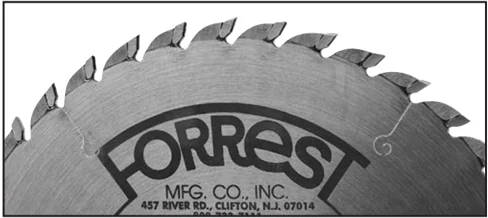
Figure 95. Forrest Woodworker II Saw Blade.
Forrest Dado Blades
- H4756—8" x 5/8" 24T Dado Blade Set
- T23267—8" x 5/8" 24T 3 Pc. Set
The world's finest dado blades cleancut all your grooves! No splintering when cross-cutting oak, ply veneers and melamine. Perfect for flat-bottomed grooves. No staggered steps or round bottoms like a wobble-dado leaves! Cuts in all directions—rip, cross-cut, miter, any depth. Super-hard carbide gives up to 300% longer life, especially good on plywoods and abrasive particle-boards. 5/8" arbor.
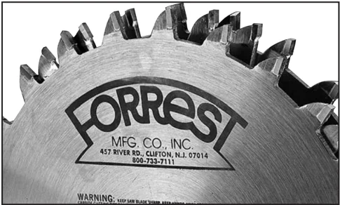
Figure 96. Forrest dado blades.
G0710—1HP Wall-Mount Dust Collector
G0710P—1HP Wall-Mount Dust Collector
G1163P—1HP Floor Model Dust Collector
G3591—30-Micron Replacement Bag
H4340—3.0-Micron Upgrade Bag
Excellent point-of-use dust collectors that can be used next to the machine with only a small amount of ducting. Specifications: 537 CFM, 7.2" static pressure, 2 cubic foot bag, and 30 micron filter. Motor is 1HP, 120V/240V, 7A/3.5A.
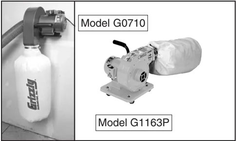
Figure 97. Point-of-use dust collectors.
order online at www.grizzly.com or call 1-800-523-4777
D3096—Featherboard Designed to lock into a standard 3/8" x 3/4" miter slot, this featherboard is fully adjustable to accommodate a wide range of workpieces.
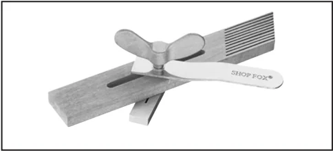
Figure 98. Model D3096 Featherboard.
T20916—Zero Clearance Insert for G0690-91 Made especially for our G0690 and G0691 Table Saws. Height is easily adjustable. Special phenolic material.
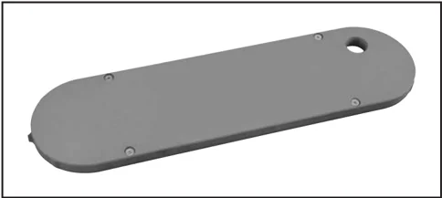
Figure 99. Model T20916 Zero Clearance Insert.
T22977—The Missing Shop Manual: Tablesaw In addition to explaining the basics of safety and setup, this handy reference will help you get the most for your money by getting the most from your equipment. From cutting dados and molding to creating jigs, you'll discover the techniques and tips you need to maximize your table saw's performance. Even if you've been woodworking for years, you'll wish this was the manual that originally came with your new table saw. 144 pgs.
Figure 100. Model T22977 The Missing Shop Manual: Tablesaw.
D4206—Clear Flexible Hose 4" x 10' D4256—45° Elbow 4" D4216—Black Flexible Hose 4" x 10' W1034—Heavy-Duty Clear Flex Hose 4" x 10' D2107—Hose Hanger 4-1/4" W1015—Y-Fitting 4" x 4" x 4" W1017—90° Elbow 4" W1019—Hose Coupler (Splice) 4" W1317—Wire Hose Clamp 4" W1007—Plastic Blast Gate 4" W1053—Anti-Static Grounding Kit We've hand picked a selection of commonly used dust collection components for machines with 4" dust ports.
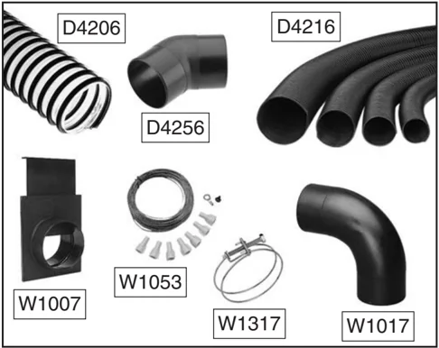
Figure 101. Dust collection accessories.
G1317—37" Outfeed Roller System This unique roller system folds down easily without tools and snaps up in place quickly when needed. Has a double level system which lets you set the rollers either in line with the table or slightly below it.
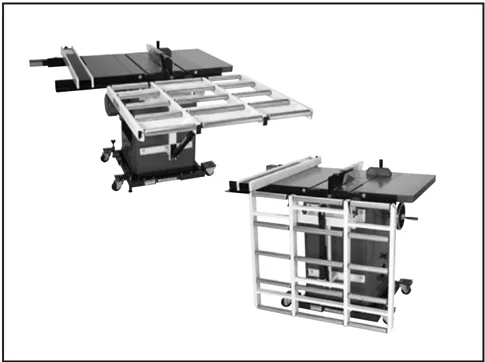
Figure 102. G1317 37" Outfeed Roller System.
order online at www.grizzly.com or call 1-800-523-4777
SECTION 7: MAINTENANCE
Schedule
For optimum performance from your machine, follow this maintenance schedule and refer to any specific instructions given in this section.
Daily Check:
- Inspect blades for damage or wear.
- Check for loose mounting bolts/arbor nut.
- Check cords, plugs, and switch for damage.
- Check for any other condition that could hamper the safe operation of this machine.
- Wipe the table clean after every use—this ensures moisture from wood dust does not remain on bare metal surfaces.
Weekly Maintenance:
- Wipe down the table surface and grooves with a lubricant and rust preventive such as SLIPIT®.
- Vacuum dust buildup from the motor housing and trunnions.
- Clean the pitch and resin from the saw blade with a cleaner like OxiSolv® Blade & Bit Cleaner.
Monthly Maintenance:
- Check/tighten the belt tension (Page 73).
Cleaning
Cleaning the Model G0690/G0691 is relatively easy. Vacuum excess wood chips and sawdust, and wipe off the remaining dust with a dry cloth. If any resin has built up, use a resin dissolving cleaner to remove it.
After cleaning, treat all unpainted cast iron and steel with a non-staining lubricant.
Occasionally it will become necessary to clean the internal parts with more than a vacuum. To do this, remove the table top and clean the internal parts with resin/pitch dissolver or mineral spirits and a stiff wire brush or steel wool. DO NOT USE WATER—WATER WILL CAUSE CAST IRON TO RUST.
Make sure the internal workings are dry before using the saw again, so that wood dust will not accumulate. If any essential lubrication is removed during cleaning, re-lubricate those areas.
Model G0690/G0691 (Mfd. 6/15+) -61-
Lubrication
An essential step for lubrication is cleaning the components before lubricating them.
This idea is critical because dust and chips build up on lubricated components and make the components hard to move. Simply adding more grease to the components with built-up grime on them will not yield smooth moving components.
Clean the components in this section with an oil/grease solvent cleaner.
If you thoroughly clean the components in this section before lubricating them, the result will be silky smooth movement when turning the handwheels, which will result in much higher enjoyment on your part!
The following are the main components that need to be lubricated:
- Trunnion Slides and Orientation Gears
- Worm Gears, Trunnion and Bearing Housing Teeth
Trunnion Slides & Orientation Gears
Clean the trunnion slides out with mineral spirits and a rag, and brush a dollop of lithium grease into each groove. Move the blade tilt back-and-forth to spread the grease (see Figure 103).
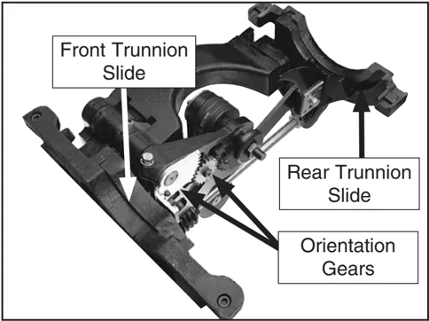
Figure 103. Trunnion slides and tilt leadscrew.
Also use a wire brush and mineral spirits to clean any debris or grime off the orientation gears, then apply lithium grease to the gears with a brush.
Worm Gears, Trunnion and Bearing Housing Teeth
Clean away any built up grime and debris with a wire brush and mineral spirits from the worm gears and the teeth on the bearing housing and trunnion. Then use a brush or rag to apply a thin coat of white lithium grease to the gears and teeth.
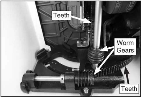
Figure 104. Worm gears and teeth.
-62- Model G0690/G0691 (Mfd. 6/15+)
SECTION 8: SERVICE
Review the troubleshooting procedures in this section if a problem develops with your machine. If you need replacement parts or additional help with a procedure, call our Technical Support. Note: Please gather the serial number and manufacture date of your machine before calling.
Troubleshooting
| Symptom | Possible Cause | Possible Solution |
|---|---|---|
| Machine does not start or a breaker trips. | 1. Locking pin installed.2. Blown fuse.3. Power supply switched OFF or at fault.4. Plug/receptacle at fault/wired wrong.5. Motor connection wired wrong.6. Wall circuit breaker tripped.7. Wiring open/has high resistance.8. Motor ON/OFF switch at fault.9. Start capacitor at fault.10. Motor at fault. | 1. Remove locking pin from ON button.2. Replace fuse/ensure no shorts.3. Ensure power supply is on/has correct voltage.4. Test for good contacts; correct the wiring.5. Correct motor wiring connections.6. Ensure circuit size is correct/replace weak breaker.7. Check/fix broken, disconnected, or corroded wires.8. Replace switch.9. Test/replace if faulty.10. Test/repair/replace. |
| Machine stalls or is underpowered. | 1. Feed rate/cutting speed too fast.2. Workpiece material unsuitable for machine.3. Workpiece crooked; fence mis-adjusted.4. Machine undersized for task.5. Run capacitor at fault.6. Belt slipping.7. Motor wired incorrectly.8. Plug/receptacle at fault.9. Pulley/sprocket slipping on shaft.10. Motor bearings at fault.11. Contactor not energized/has poor contacts.12. Motor overheated.13. Motor at fault. | 1. Decrease feed rate/cutting speed.2. Only cut wood/ensure moisture is below 20%.3. Straighten or replace workpiece/adjust fence.4. Use correct blade/reduce feed rate or depth of cut.5. Test/repair/replace.6. Tension/replace belt (Page 73).7. Wire motor correctly.8. Test for good contacts/correct wiring.9. Replace loose pulley/shaft.10. Test/repair/replace.11. Test all legs for power/replace if faulty.12. Clean motor, let cool, and reduce workload.13. Test/repair/replace. |
| Machine has vibration or noisy operation. | 1. Motor or component loose.2. Blade at fault.3. Belts worn or loose.4. Pulley loose.5. Motor mount loose/broken.6. Machine incorrectly mounted.7. Arbor pulley loose.8. Motor fan rubbing on fan cover.9. Arbor bearings at fault.10. Motor bearings at fault. | 1. Inspect/replace damaged bolts/nuts, and re-tighten with thread locking fluid.2. Replace warped/bent blade; resharpen dull blade.3. Tension/replace belts (Page 73).4. Realign/replace shaft, pulley, setscrew, and key.5. Tighten/replace.6. Tighten mounting bolts; relocate/shim machine.7. Retighten/replace arbor pulley.8. Fix/replace fan cover; replace loose/damaged fan.9. Replace arbor housing bearings; replace arbor.10. Test by rotating shaft; grinding/loose shaft requires bearing replacement. |
| Symptom | Possible Cause | Possible Solution |
|---|---|---|
| Blade is not aligned with miter slot or fence. | 1. Blade is warped.2. Table top is not parallel to blade.3. Fence is not parallel to blade. | 1. Replace blade (Page 36).2. Make table parallel to blade (Page 67).3. Make fence parallel to blade (Page 69). |
| Blade does not reach 90°. | 1. 90° stop bolt is out of adjustment.2. Sawdust stuck on stop bolt. | 1. Adjust 90° stop bolt (Page 65).2. Clean sawdust off stop bolt. |
| Blade hits insert at 45°. | 1. 45° stop bolt is out of adjustment.2. Sawdust stuck on stop bolt.3. Hole in insert is inadequate.4. Table out of alignment.5. Blade position is incorrect. | 1. Adjust 45° stop bolt (Page 65).2. Clean sawdust off stop bolt.3. File or mill the hole in the insert.4. Align blade to the table (Page 67).5. Adjust blade position. |
| Board binds or burns when feeding through table saw. | 1. Dull blade.2. Blade is warped.3. Fence is not parallel to blade.4. Table top is not parallel to blade. | 1. Replace blade.2. Replace blade (Page 36).3. Make fence parallel to blade (Page 69).4. Make table parallel to blade (Page 67). |
Blade Tilt Stops
The table saw features stop bolts that stop the blade exactly at 45° and 90° when tilting it with the handwheel. The stops have been set at the factory and should require no adjustments, unless you notice that your cuts are not accurate.
Note: The tilt scale reads "0" when the blade is 90° to the table.
Tools Needed
| Tool | Qty |
|---|---|
| 90° Square | 1 |
| 45° Square | 1 |
| Hex Wrench 3mm | 1 |
| Wrench 10mm | 1 |
| Wrench 13mm | 1 |
Setting 90° Stop Bolt
-
DISCONNECT THE SAW FROM POWER!
-
Raise the blade as high as it will go, then tilt it toward 0° until it stops and cannot be tilted any more.
-
Place a 90° square against the table and blade so it contacts the blade evenly from bottom to top, as shown in Figure 105. Make sure a blade tooth does not obstruct the placement of the square.
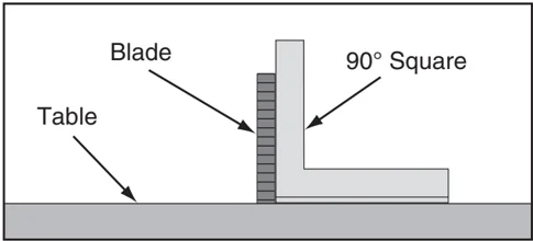
Figure 105. Checking blade at 90°.
—If the blade is 90° to the table, then adjustments do not need to be made. Make sure the tilt indicator arrow shown in Figure 106 points to the 0° mark on the scale. Adjust the position by loosening the button head screw, moving the indicator with your fingers, then tightening the screw.
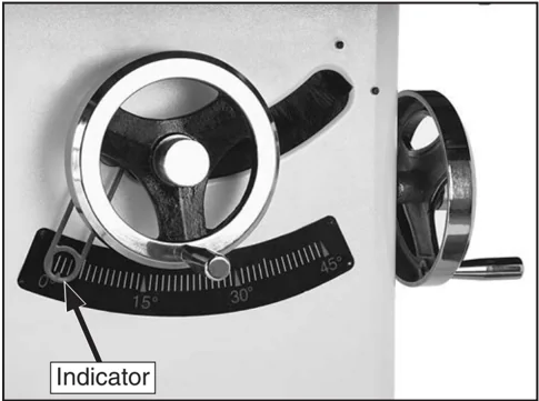
Figure 106. Tilt indicator arrow.
—If the blade is not 90° to the table, you will need to adjust the 90° stop screw. Proceed to the next step.
-
Tilt the blade away from 0° by about 5°, so there is room for the stop bolt to move.
-
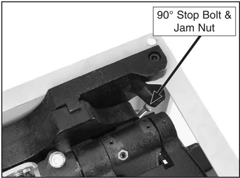
Open the motor access cover, loosen the jam nut shown in Figures 107 and 108, adjust the stop bolt up or down according to how far off the blade was from 90°, then repeat Steps 2-3 until the blade stops at 90°.
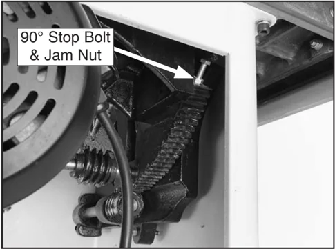
Figure 107. 90° stop bolt and jam nut.
-If the blade is 45° to the table, then adjustments do not need to be made.
-If the blade is not 45° to the table, you will need to adjust the 45° stop screw. Proceed to the next step.
-
Tilt the blade to 15°, so there is room for the stop bolt to move.
-
Remove the dust port to access the stop bolt.
-
Loosen the jam nut on the 45° stop bolt (see Figure 110) with a 13mm wrench, adjust the stop bolt up or down according to how far off the blade was from 45°.
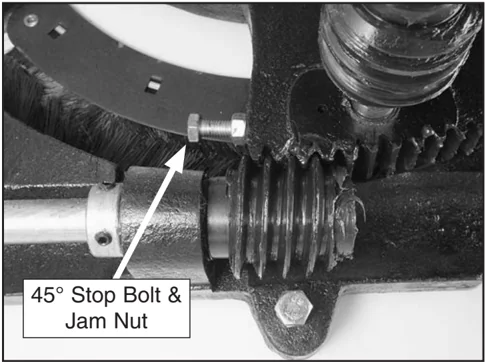
Figure 110. 45° stop bolt and jam nut.
-
Continue adjusting the stop bolt until it contacts the cabinet when the blade is at 45°, then tighten the jam nut.
-
Close the dust port.
-
Tighten the jam nut, then close the motor cover.
Setting 45° Stop Bolt
-
DISCONNECT THE SAW FROM POWER!
-
Raise the blade as high as it will go, then tilt it towards 45° until it stops and cannot be tilted any more.
-
Place a 45° square against the table and blade so it contacts the blade evenly from bottom to top, as shown in Figure 109. Make sure a blade tooth does not obstruct the placement of the square.
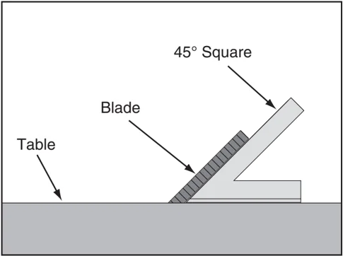
Figure 109. Checking blade at 45°.
Miter Slot to Blade Parallelism
Tools Needed
- Adjustable Square ........ 1
- Metal Shim Stock ........ As Needed
- Marker ........ 1
Your table saw will give the best results if the miter slot and the rip fence are adjusted parallel to the blade. If either of these are not exactly parallel, your cuts and your finished work will be lower in quality, but more importantly, the risk of kickback will be increased. Take the time to adjust your table saw properly. A few minutes now will be time well spent.
To adjust the blade parallel to the miter slot:
- DISCONNECT THE SAW FROM POWER!
- Use an adjustable square to measure the distance from the miter slot to a carbide tip on the blade, as shown in Figure 111. Make sure that the face of the adjustable square is even along the miter slot.
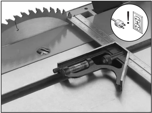
Figure 111. Example of adjusting blade to miter slot.
- With the end of the adjustable square just touching the tip, lock the square in place. Now, mark the carbide tip with a marker where you made this measurement.
! CAUTION The saw blade is dangerously sharp. Use extra care or wear gloves when handling the blade or working near it.
- Rotate the marked blade tip to the other end of the table insert.
- Slide the adjustable square down to the other end of the table insert, and compare the distance from the marked blade tip to the end of the adjustable square. —If the blade tip does not touch the end of the adjustable square similar to the first measurement, the table will need to be adjusted. Proceed to Step 6. —If the blade tip measurement is the same on both sides, go to Step 7.
- To adjust the table, loosen the four cap screws in the table mounting locations (see Figure 112) and slightly tap the table in the needed direction. Repeat Steps 2–5 until the blade and miter slot are parallel.
- Tighten the table mounting cap screws in a criss-cross, alternating manner.
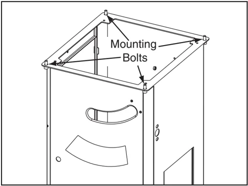
Figure 112. Table mounting bolts.
Model G0690/G0691 (Mfd. 6/15+) -67-
Spreader or Riving Knife Alignment
Checking Alignment
The blade guard spreader and riving knife must be aligned with the blade when installed. If the spreader/riving knife is not aligned with the blade, then the workpiece will before forced sideways during the cut, which will increase the risk of kick-back.
- Tools Needed ........ Qty
- Straightedge ........ 1
To check the spreader/riving knife alignment:
- DISCONNECT THE SAW FROM POWER!
- Raise the saw blade to the maximum height so you have easy working access.
- Place the straightedge against the top and bottom of blade and spreader/riving knife, as shown in Figure 113. The spreader/riving knife should be parallel with the blade along its length at both positions, and it will be in the "Alignment Zone," as shown in Figure 114.
 Figure 113. Checking top and bottom riving knife parallelism with blade.
 Figure 114. Spreader/riving knife alignment zone.
—If the spreader/riving knife is not parallel with the blade and inside the alignment zone, then it needs to be adjusted. Proceed to Adjusting Alignment instructions.
—If the spreader/riving knife is not parallel with the blade at either the top or bottom, it may be bent.
- Remove the spreader/riving knife and place it on a flat surface and check to see if the spreader/riving knife lays evenly along its length.
—If the spreader/riving knife does not lay evenly, proceed to Adjusting Bent Spreader/Riving Knife on Page 69.
Adjusting Alignment
The spreader/riving knife mounting position can be adjusted into alignment with the blade using the set screws on the spreader/riving knife mounting block.
- Possible Tools Needed ........ Qty
- Hex Wrench 3mm ........ 1
- Hex Wrench 5mm ........ 1
To adjust the spreader/riving knife position:
- DISCONNECT THE SAW FROM POWER!
- Remove the table insert.
-68- Model G0690/G0691 (Mfd. 6/15+)
- Loosen the two cap screws on the mounting block, then adjust either the top or bottom control set screws or side control set screws (see Figure 115) to move it the needed direction.
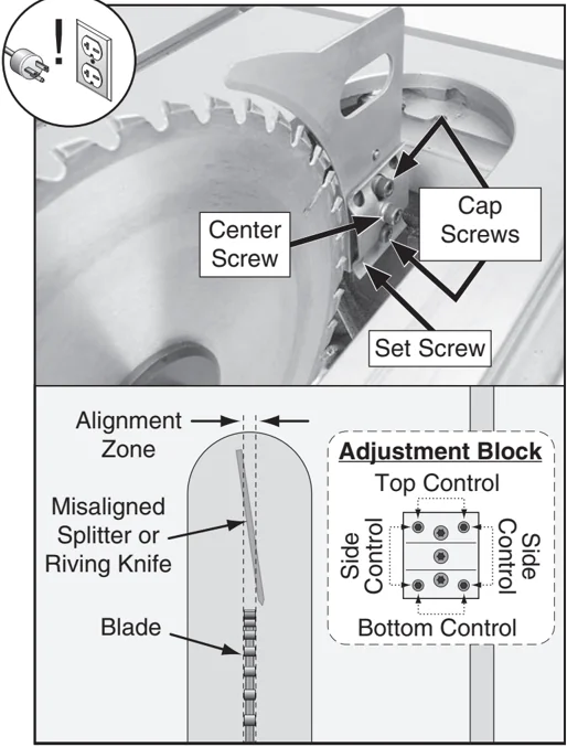
Figure 115. Set screws for adjusting spreader/riving knife position.
Top and Bottom Control: To move the top of the spreader/riving knife right or left (and the bottom of the spreader/riving knife in the opposite direction), adjust the top and bottom pair of set screws on the mounting block an equal amount in the opposite direction.
Side Control: To move the front of the spreader/riving knife left or right (and the rear of the spreader/riving knife in the opposite direction), adjust each pair of side control set screws an equal amount in the opposite direction.
Note: To adjust how tightly the mounting block holds the spreader/riving knife, adjust the center screw.
-
Reinstall the table insert.
-
Follow Checking Alignment, Steps 1–3.
—If the spreader/riving knife is in the alignment zone, no additional steps are necessary.
—If the spreader/riving knife is still not in the alignment zone, continue adjusting the set screws on the mounting block as necessary to correctly position the spreader/riving knife.
- Tighten the two cap screws on the mounting block to secure the spreader/riving knife adjustment.
Adjusting Bent Spreader/Riving Knife
-
DISCONNECT THE SAW FROM POWER!
-
Bend the spreader or riving knife by hand while installed, then follow Steps 1–□ in Checking Alignment to determine if it is parallel with the blade and inside the "Alignment Zone" (refer to Checking Alignment).
—If this doesn't work, remove it to straighten.
—If you cannot straighten it properly, replace it.
Fence Adjustments
There are four main adjustments for the fence: square, height, parallelism, and clamping pressure. Keep in mind that these adjustments are interconnected and some trial-and-error may be needed to achieve satisfactory results.
Tools Needed Qty
- Hex Wrench 6mm ........ 1
- Square ........ 1
- Felt-Tipped Marker ........ 1
Square and Height
The fence face must be square to the table in order to produce square cuts. Also, the fence should be adjusted high enough off the table that it does not drag across the surface.
Model G0690/G0691 (Mfd. 6/15+) -69-
To check/adjust the fence height and squareness to the table:
- DISCONNECT THE SAW FROM POWER!
- Place a square on the table against the face of the fence (Figure 116) to check if the fence is square to the table. —If the fence is not square to the table, proceed to Step 3. —If the fence is square to the table, skip ahead to Step 4.
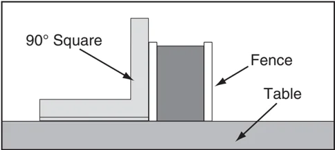
Figure 116. Checking if fence is square to table.
- Adjust the set screws (Figure 117) on top of the fence bracket to ensure the fence face is 90° to the table, then tighten the knurled lock nuts.
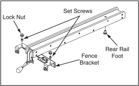
Figure 117. Fence components used to adjust fence height and squareness to table.
-
Look at the gap between the fence and the table top. —If the gap is approximately 1/16" and even from the front of the table to the back, then no additional adjustments are necessary. —If the gap is uneven, if the fence height is more than 1/8", or if the fence touches the table, then continue with Step 5.
-
Adjust the fence height with the rear rail foot until the gap between the table and the fence is approximately 1/16" and even from the front of the table to the back.
Note: If the front end of the fence needs to be adjusted up or down, use the set screws from Figure 117; however, turn them in even increments and recheck the squareness afterwards.
Clamping Pressure and Parallelism
Set screws on the rear side of the fence bracket adjust the clamping pressure to hold your fence securely, and position the fence parallel to the blade.
To adjust the fence clamping pressure and parallelism to the blade:
- DISCONNECT THE SAW FROM POWER!
- Remove the fence.
- Equally adjust the set screws shown in Figure 118 on the rear side of the front bracket as necessary until the clamping pressure is strong enough that the fence will not move as pressure is applied against it.
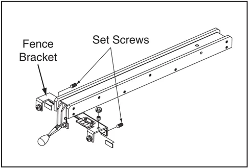
Figure 118. Location of set screws used to adjust fence parallelism and clamping pressure.
- Place the fence approximately 4" away from the blade.
-
Measure the distance between the fence and the front of the blade at one end of the table insert, then mark the tooth that you measured from with a felt-tipped marker.
-
Rotate the blade to the other end of the table insert (Figure 119), and recheck the distance between the fence and the blade to ensure they are parallel.
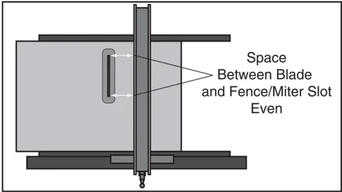
Figure 119. Example of fence aligned parallel to miter slot.
- Use trial-and-error to adjust the set screws so the fence is parallel to the blade and the clamping pressure is sufficient.
Optional: Some woodworkers prefer to offset the rear of the fence $1/64"$ from the blade, as shown in Figure 120, to help prevent the workpiece from binding and burning.
The argument is that this offset adjustment reduces the chance of kickback by alleviating potential binding that may occur between the backside of the blade and fence. The trade-off is slightly less accurate cuts.
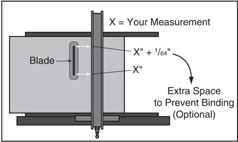
Figure 120. Adjusting fence with a $1/64"$ offset.
Fence Scale Calibration
The fence scale indicator window, shown in Figure 121, can be calibrated with the fence scale if you notice that your cuts do not accurately match what is shown on the fence scale.
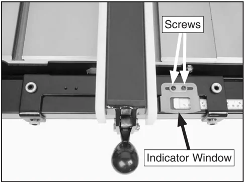
Figure 121. Fence indicator window.
The indicator adjusts by loosening the two mounting screws and sliding it in the desired direction.
Tools Needed
- Hex Wrench 2.5mm ........ 1
- Scrap Piece of Wood ........ 1
To calibrate the fence scale indicator windows:
-
Position and lock the fence at 13", as indicated by the scale, cut your scrap piece of wood.
-
Reposition and lock the fence at 12", as indicated by the scale.
-
Flip your scrap piece of wood over, placing the side that was cut in Step 2 against the fence, and cut your scrap piece of wood.
-
Measure the width of the freshly cut workpiece with a tape measure. The workpiece width should be exactly 12". If it is not, then adjust the indicator window to match the width of the workpiece.
Miter Gauge Adjustments
The miter gauge can be adjusted so it is perpendicular to the blade and snug in the T-slot.
Tools Needed
| Tool | Qty |
|---|---|
| 90° Square | 1 |
| 45° Square | 1 |
| Hex Wrench 2.5mm | 1 |
| Hex Wrench 2mm | 1 |
| Hex Wrench 3mm | 1 |
Checking/Setting 90° Stops
- DISCONNECT THE SAW FROM POWER!
- Slide the miter gauge into the T-slot on the table.
- Loosen the miter gauge lock knob, pull out the positive stop knob, then pivot the miter gauge body to 90° so the stop knob springs into position.
- Place the square evenly against the face of the miter gauge and the blade, as shown in Figure 122.
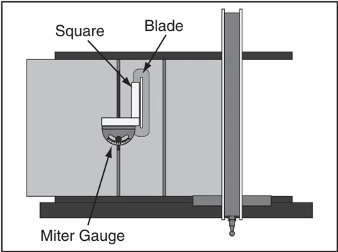
Figure 122. Checking 90° stop on miter gauge.
—If the square touches the miter body and the body of the blade (not the teeth) evenly at the same time, then it is square to the blade and the 90° stop is set correctly. No further adjustments are necessary.
—If the square does not touch the miter body and blade body evenly at the same time, then proceed to Step 5.
- Loosen the button head cap screws on the positive stop knob block (see Figure 123), adjust the miter body until it is flush with the square, then tighten the screws.
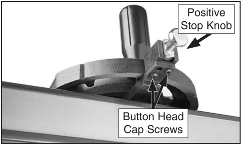
Figure 123. Screws for adjusting miter gauge body.
- Loosen the screw on the front of the miter bar, adjust the pointer to 0°, then tighten the screw.
Adjusting Miter Bar Tightness
The miter bar can be adjusted so it fits more tightly in the miter slot.
To adjust the miter bar tightness:
- Loosen the cap screw on each guide block (Figure 124), adjust the set screws as needed, then tighten the cap screw.
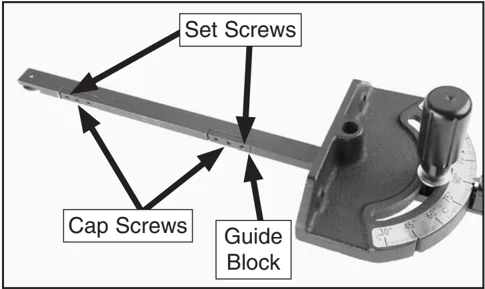
Figure 124. Screws for adjusting miter bar in miter slot.
Model G0690/G0691 (Mfd. □/□□+)
Belt Tension & Replacement
The three V-belts stretch slightly as the saw is used. Most of the belt stretching will happen during the first 16 hours of use, but it may continue in small increments through continued use.
Tools Needed
- Wrenches 18mm ........ 2
Tensioning Belt
- DISCONNECT THE SAW FROM POWER!
- Lower the blade completely, then open the motor cabinet.
- Loosen the hex nuts on the motor shown in Figure 125, and pivot the motor up and down to make sure that it is movable.
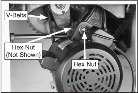
Figure 125. Motor mounting nut.
- Press down on the motor with one hand to keep the belt tension tight and tighten the hex nuts.
- Press each V-belt in the center to check belt tension.
The belts are correctly tensioned when there is approximately 1/2" deflection when they are pushed with moderate pressure, as shown in Figure 126.
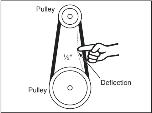
Figure 126. Checking belt tension.
—If there is more than 1/2" deflection when the V-belts are pushed with moderate pressure, loosen the hex nuts, adjust the motor downward, then tighten the hex nuts.
- Close the motor access cover.
Replacing Belt
- DISCONNECT THE SAW FROM POWER!
- Lower the blade completely, then open the motor access cover.
- Loosen the hex nuts that secure the motor (see Figure 125) and raise the motor fully to remove tension on the V-belts. Roll the V-belts off of the arbor and motor pulleys.
- While continuing to raise the motor, install a new matching set of V-belts onto the pulleys, lower the motor to tension the V-belts, then tighten the hex nuts.
- Follow Step 5 in the Tensioning Belt sub-section to check V-belt tension.
- Close the motor access cover.
Model G0690/G0691 (Mfd. 6/15+) -73-