SECTION 5: ACCESSORIES
WARNING Installing unapproved accessories may cause machine to malfunction, resulting in serious personal injury or machine damage. To reduce this risk, only install accessories recommended for this machine by Grizzly.
NOTICE Refer to our website or latest catalog for additional recommended accessories.
W1218A—Rotacator™ Precision Planer Tool The Rotacator is a dial indicator on a magnetic base, designed for quickly and accurately setting the critical tolerances needed when making planer adjustments. Perfect for adjusting infeed/outfeed rollers, pressure bars, chip breakers, and bed rollers. Also a great setup tool for other machines! Accurate to 0.001". Indicator rotates 360°
 Figure 31. Rotacator™ Precision Planer Tool.
T27695—15" Helical Spiral Cutterhead for Planers These helical spiral cutterheads feature four spirals and replaceable carbide inserts for providing an incredible finish.
 Figure 32. T27395 !5" Helical Spiral Cutterhead.
For G1021X2: H9893—Indexable Carbide Inserts, 10 Pack These Indexable Carbide Inserts are designed for use in spiral or helical cutterhead systems and made to last up to 10 times longer than a set of HSS steel inserts. Made of solid carbide. Size: 15 x 15 x 2.5mm.
 Figure 33. H9893 Indexable Carbide Inserts.
order online at www.grizzly.com or call 1-800-523-4777 -32-

For G1021Z: G6701—HSS Replacement Knives, Set of 3 These M-2 HSS planer knife sets are hardened and tempered to 62–64 Rockwell and balanced to within 1 gram.
 Figure 34. Grizzly planer blades.
D2273— Single Roller Stand This super heavy-duty roller stand features convenient hand knobs for fast height adjustment. Invaluable for supporting work on machines of varying heights. Adjusts from 26-5/8" to 45". 250 lb. capacity.
 Figure 35. D2273 Single Roller Stand.
Basic Eye Protection T20501—Face Shield Crown Protector 4" T20502—Face Shield Crown Protector 7" T20503—Face Shield Window T20451—“Kirova” Clear Safety Glasses T20452—“Kirova” Anti-Reflective S. Glasses T20456—DAKURA Safety Glasses, Black/Clear
 Figure 36. Assortment of basic eye protection.
H4978—Deluxe Earmuffs - 27dB H4979—Twin Cup Hearing Protector - 29dB T20446—Classic Earplugs, 200-pair - 31dB Protect yourself comfortably with a pair of cushioned earmuffs. Especially important if you or employees operate for hours at a time.
 Figure 37. Hearing protection.
order online at www.grizzly.com or call 1-800-523-4777
G5562—SLIPIT® 1 Qt. Gel G5563—SLIPIT® 12 Oz. Spray G2871—Boeshield® T-9 12 Oz. Spray G2870—Boeshield® T-9 4 Oz. Spray H3788—G96® Gun Treatment 12 Oz. Spray H3789—G96® Gun Treatment 4.5 Oz. Spray

Figure 38. Recommended products for protecting unpainted cast iron/steel parts on machinery.
D4206—Clear Flexible Hose 4" x 10' W1034—Heavy-Duty Clear Flex Hose 4" x 10' W1015—Y-Fitting 4" x 4" x 4" W1017—90° Elbow 4" W1019—Hose Coupler (Splice) 4" W1317—Wire Hose Clamp 4" W1007—Plastic Blast Gate 4" W1053—Anti-Static Grounding Kit We've hand-picked a selection of commonly used dust-collection components for machines with 4" dust ports.
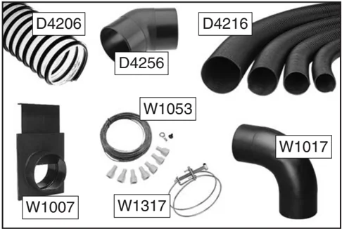
Figure 39. Dust-collection accessories.
SB1365—South Bend Way Oil-ISO 68 Engineered for the high pressure exerted on horizontal or vertical ways and slides. Protects against rust and corrosion. Ensures stick-free, smooth motion which maximizes finishes and extends the life of your machine. Won’t gum up! 12 oz. AMGA#2 (ISO 68 Equivalent)

Figure 40. SB1365 Way Oil.
T28042—Moly-D Industrial Gear Oil-ISO 320 This industrial gear oil from Primrose has been developed specifically for the high temperatures and pressures typical of modern industrial applications. 1-gallon size.
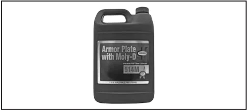
Figure 41. T28042 Gear Oil.
T26419—Syn-O-Gen Synthetic Grease 100% pure synthesized hydrocarbon basestocks compounded with special thickeners and additives make Syn-O-Gen non-melt, tacky, and water resistant. Extremely low pour point, high temperature oxidation, and thermal stability produce a grease unmatched in performance.
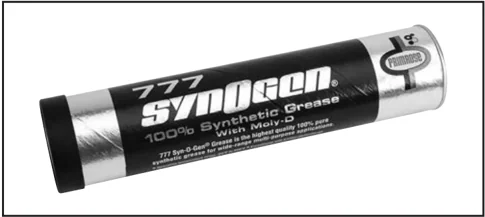
Figure 42. T26419 Synthetic Grease.
order online at www.grizzly.com or call 1-800-523-4777
-34-
SECTION 6: MAINTENANCE
! WARNING To reduce risk of shock or accidental startup, always disconnect machine from power before adjustments, maintenance, or service.
Schedule
For optimum performance from your machine, follow this maintenance schedule and refer to any specific instructions given in this section.
Note: This maintenance schedule is based on average daily usage. Adjust the maintenance schedule to match your usage, to keep your planer running smoothly, and to protect your investment.
Every 8 Hours of Operation:
- Clean machine and protect unpainted cast-iron surfaces.
- Lubricate feed roller bushings (Page 36).
- Tighten loose mounting bolts.
- Check/sharpen/replace damaged or worn knives/inserts (Page 28).
- Check/repair/replace worn or damaged wires.
- Resolve any other unsafe condition.
Every 40 Hours of Operation:
- Clean cutterhead and, for G1021Z, check knife height (Page 28).
- Lubricate table columns and leadscrews (Page 36).
Every 160 Hours of Operation:
- Check/tension/replace V-belts (Page 41).
- Clean/vacuum dust buildup from inside cabinet and off motor.
- Lubricate table height worm gear (Page 36).
- Lubricate table height chain and sprockets (Page 36).
- Lubricate drive chain and sprockets (Page 37).
Yearly:
- Change gearbox oil (Page 37).
Cleaning & Protecting
Vacuum excess wood chips and sawdust, and wipe off the remaining dust with a dry cloth. If any resin has built up, use a resin-dissolving cleaner to remove it.
Protect the unpainted cast-iron table by wiping it clean after every use—this ensures moisture from wood dust does not remain on bare metal surfaces. Keep the table rust-free with regular applications of products like G96® Gun Treatment, SLIPIT®, or Boeshield® T-9 (see Page 34 for more details).
Lubrication
NOTICE Failure to follow reasonable lubrication practices as instructed in this manual for your machine could lead to premature failure of components and void the warranty.
This planer features bearings that are lubricated and sealed at the factory. These bearing do not require any further attention unless they need to be replaced. If a bearing fails, your planer will probably develop a noticeable rumble or vibration, which will increase when the machine is under a load. The bearings are standard sizes and can be replaced through Grizzly.
Follow the maintenance schedule on this page and the procedures beginning on Page 36 to properly lubricate the other planer components, which are essential for long life and trouble-free operation of your planer.
Feed Roller Bushings
- Oil Type ........ SB1365 or ISO-68 Equivalent
- Oil Amount ........ 2–3 Drops
- Frequency ........ Every 8 Hours of Operation
The infeed and outfeed rollers rotate inside bushing blocks on both ends of the rollers. Add 2–3 drops of ISO 68 machine oil to the center hole of the four feed roller tension adjustment bolts on top of the head casting, as shown in Figure 43.
 Figure 43. Example of lubrication locations for feed roller bushings.
Columns & Leadscrews
- Oil Type ........ SB1365 or ISO-68 Equivalent
- Oil Amount ........ Thin Coat
- Grease Type ........ NLGI#2 Equivalent
- Frequency ........ Every 40 Hours of Operation
The table rides on the columns and is moved by the rotation of the leadscrews inside the columns. Loosen the dust sleeve (see Figure 44) to access the columns and leadscrews. Apply a thin coat of ISO 68 machine oil to the outside surface of the columns and brush on a light application of multi-purpose grease to the leadscrew threads. Move the table up and down to distribute the lubricant.
 Figure 44. Location of column and leadscrew.
Table Height Worm Gear
- Grease Type ........ NLGI#2 Equivalent
- Frequency ........ Every 160 Hours of Operation
Remove the three cap screws that secure the worm gear housing (see Figure 45), then lift the housing and handwheel assembly off the machine. Clean away any debris from the housing and gears, then brush on a moderate amount of multi-purpose grease to the gear teeth.
 Figure 45. Example of table height worm gear housing.
Table Height Chain & Sprockets
- Grease Type ........ NLGI#2 Equivalent
- Frequency ........ Every 160 Hours of Operation
The table leadscrews are synchronized by the table height chain and sprockets located underneath the planer base (see Figure 46). Use shop rags and mineral spirits to clean away debris and grime, then brush on a light coat of multi-purpose grease to the chain and sprockets.
 Figure 46. Example of table height chain and sprockets as viewed from underneath the base.
Drive Chain & Sprockets
- Grease Type ........ T26419 Synthetic Grease
- Frequency ........ Every 160 Hours of Operation
The infeed and outfeed rollers receive the transferred power from the cutterhead through the drive chain system on the right side of the machine, as shown in Figure 47.
Remove the table height handwheel and the safety covers attached to the inside of the drive chain cover, then remove the cover to access these parts.
Use shop rags and mineral spirits to clean away any debris and grime, then brush on a light coat of multi-purpose grease to the chain and sprockets.
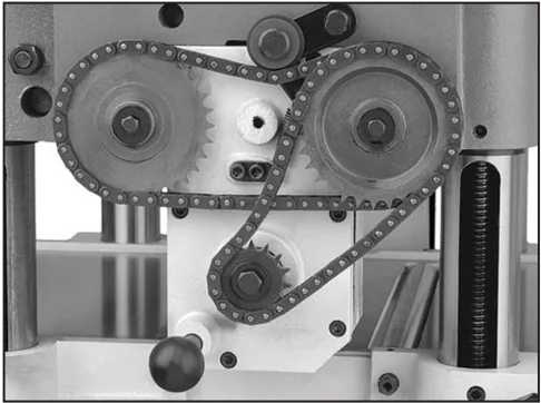
Figure 47. Drive chains and sprockets for infeed and outfeed rollers.
Gearbox Oil
- Oil Type ........ T28042 or ISO-320 Equivalent
- Oil Amount ........ 20 Oz.
- Frequency ........ After First 20 Hours, Then Yearly
Note: We recommend that you replace the gearbox oil after the first 20 hours of operation. This is a normal break-in procedure and will help maximize the service life of the machine by flushing away any particles from the break-in and manufacturing process.
Although it is not necessary to remove the drive chain cover to access the fill and drain plugs, it is more convenient to do so (see Figures 48–49). Replace the gearbox oil with ISO 320 or equivalent oil until it just reaches the fill plug.
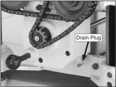
Figure 48. Location of gearbox drain plug.
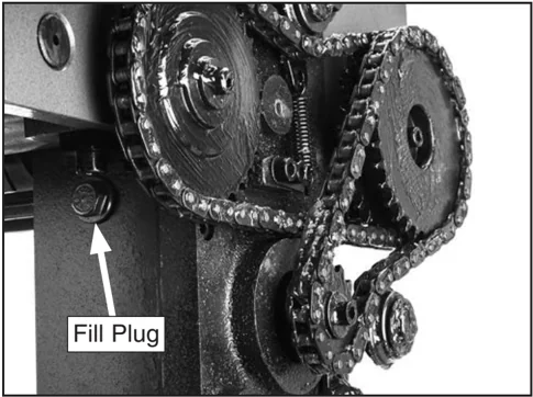
Figure 49. Example of gearbox fill plug.
SECTION 7: SERVICE
Review the troubleshooting procedures in this section if a problem develops with your machine. If you need replacement parts or additional help with a procedure, call our Technical Support. Note: Please gather the serial number and manufacture date of your machine before calling.
Troubleshooting
Motor & Electrical
| Symptom | Possible Cause | Possible Solution |
|---|---|---|
| Machine does not start, or power-supply fuse/breaker trips immediately after startup. | 1. Stop button depressed/at fault.2. Incorrect power supply voltage or circuit size.3. Thermal overload relay has tripped.4. Power supply circuit breaker tripped or fuse blown.5. Motor wires connected incorrectly.6. Wiring open/has high resistance.7. Start button switch at fault.8. Centrifugal switch/contact points at fault.9. Start capacitor at fault.10. Thermal overload relay has tripped.11. Contactor not energized; has poor contacts.12. Motor at fault. | 1. Rotate button head to reset; replace if at fault.2. Ensure correct power supply voltage and circuit size.3. Reset; adjust trip load dial if necessary; replace.4. Ensure circuit is sized correctly and free of shorts. Reset circuit breaker or replace fuse.5. Correct motor wiring connections.6. Check/fix broken, disconnected, or corroded wires.7. Replace switch.8. Adjust/replace centrifugal switch/contact points if available.9. Test/replace if at fault.10. Reset; adjust trip load dial if necessary; replace.11. Test all legs for power/replace.12. Test/repair/replace. |
| Machine stalls or is underpowered. | 1. Machine undersized for task.2. Workpiece not suitable for machine.3. Motor overheated, causing thermal overload to trip.4. Belt(s) slipping; oil/grease on belt(s).5. Dull knives/inserts.6. Dust-collection problem causing internal components to clog up with shavings.7. Motor wired incorrectly.8. Centrifugal switch/contact points at fault.9. Run capacitor at fault.10. Pulley slipping on shaft.11. Contactor not energized/has poor contacts.12. Motor bearings at fault. | 1. Reduce feed rate/depth of cut.2. Only cut wood/ensure moisture is below 20%.3. Allow motor to cool, reset overload if necessary, and reduce depth of cut.4. Clean/tension/replace belt(s) (Page 41); align pulleys (Page 42).5. Sharpen/replace knives (Page 28), or replace inserts (Page 31).6. Clear blockages in dust chute/ducting, ensure dust collector is operating efficiently.7. Wire motor correctly.8. Adjust/replace centrifugal switch/contact points if available.9. Test/repair/replace.10. Tighten loose pulley; replace pulley/shaft if damaged.11. Test all legs for power/replace.12. Test/repair/replace. |
-38-
Motor & Electrical (Cont.)
| Symptom | Possible Cause | Possible Solution |
|---|---|---|
| Machine has vibration or noisy operation. | 1. Motor or component loose.2. V-belt(s) worn, loose, or slapping cover.3. Pulley loose.4. Bed rollers protruding unevenly.5. Plastic chip deflector hitting knives.6. Motor fan rubbing on fan cover.7. Knives/gibs at fault.8. Cutterhead bearings at fault.9. Motor bearings at fault. | 1. Inspect/tighten loose bolts/nuts; replace damaged components.2. Tension/replace belts as a matched set (Page 41).3. Re-align/replace shaft, pulley set screw, and key.4. Adjust bed rollers (Page 27).5. Adjust chip deflector (Page 47); replace if necessary.6. Fix/replace fan cover; replace loose/damaged fan.7. Sharpen/replace knives; set knife alignment/height correctly (Page 28).8. Replace bearing(s).9. Test by rotating shaft; rotational grinding/loose shaft requires bearing replacement. |
Machine Operation
| Symptom | Possible Cause | Possible Solution |
|---|---|---|
| Excessive snipe (gouge in end of board that is uneven with rest of cut).Note: A small amount of snipe is inevitable with all types of planers. The key is minimizing it as much as possible. | 1. One or both of bed rollers are set too high.2. Outfeed extension slopes down or is not level with main table.3. Chip breaker set too low.4. Workpiece is not supported as it leaves planer.5. Some snipe is inevitable. | 1. Lower bed rollers (Page 27).2. Shim outfeed extension wing level with main table.3. Raise height of chip breaker (Page 43).4. Hold workpiece up slightly as it leaves outfeed end of planer.5. Plane lumber longer than your intended workpiece length, then cut off excess after planing complete. |
| Workpiece stops/ slows in middle of cut. | 1. Taking too heavy of a cut.2. One or both of bed rollers are set too low or too high.3. Chip breaker or pressure bar set too low.4. Feed rollers set too low or too high.5. Pitch and glue buildup on planer components. | 1. Take a lighter cut.2. Adjust bed rollers (Page 27).3. Raise height of chip breaker or pressure bar (Page 43).4. Adjust feed rollers (Page 43).5. Clean internal cutterhead components with a pitch/resin-dissolving solvent. |
| Chipping (consistent pattern). | 1. Knots or conflicting grain direction in wood.2. Taking too deep of a cut.3. Feeding workpiece too fast.4. Mis-adjusted chip breaker.5. Nicked or chipped knife/insert. | 1. Inspect workpiece for knots and grain direction; only use clean stock, and cut WITH the grain.2. Take a smaller depth of cut. (Reduce cutting depth when planing hard woods.)3. Slow down feed rate.4. Adjust both sides of chip breaker to correct height.5. Replace affected knife (Page 28), or have it sharpened; rotate/replace insert (Page 31). |
| Chipping/indentation in workpiece surface (inconsistent pattern). | 1. Chips aren't being properly expelled from cutterhead.2. Chip breaker not set correctly. | 1. Use a proper dust-collection system.2. Correctly adjust chip breaker (Page 43). |
Machine Operation (Cont.)
| Symptom | Possible Cause | Possible Solution |
|---|---|---|
| Fuzzy grain. | 1. Wood may have high moisture content or surface wetness.2. Dull knives/inserts. | 1. Check moisture content is below 20% and allow to dry if moisture is too high.2. Replace knives (Page 28) or have them professionally sharpened; rotate/replace inserts (Page 31). |
| Long lines or ridges that run along length of board. | 1. Nicked or chipped knife/inserts. | 1. Replace knives (Page 28) or have them professionally sharpened; rotate/replace inserts (Page 31). |
| Uneven cutting marks, wavy surface, or chatter marks across face of board. | 1. Feeding workpiece too fast.2. Chip breaker or pressure bar set unevenly or not low enough.3. Knives not installed evenly/inserts not properly installed.4. Worn cutterhead bearings. | 1. Slow down feed rate.2. Adjust height of chip breaker (Page 43).3. Adjust knives with knife gauge (Page 28); remove inserts, properly clean mounting pocket and reinstall (Page 31).4. Replace cutterhead bearings. |
| Glossy surface. | 1. Knives/inserts are dull.2. Feeding workpiece too slow.3. Cutting depth too shallow. | 1. Replace knives (Page 28) or have them professionally sharpened; rotate/replace inserts (Page 31).2. Increase feed rate.3. Increase depth of cut. |
| If workpiece twists in machine. | 1. Feed rollers not parallel with table. | 1. Adjust feed rollers (Page 43). |
-40- G1021X2/G1021Z (Mfd. Since 11/20)
Tensioning/Replacing V-Belts
NOTICE
After approximately 16 hours of operation, V-belts will stretch and seat into pulley grooves and need to be properly tensioned to avoid severely reducing life of V-belts.
Three V-belts transfer power from the motor to the cutterhead, and then to the infeed and outfeed rollers with the use of the drive chain system. To ensure efficient transfer of power to these systems, make sure the V-belts are always properly tensioned and in good condition.
If the V-belts are worn, cracked, or damaged, replace them. Always replace the V-belts with a matched set of three, or belt tension may not be even among the belts, causing premature belt failure.
CAUTION
V-belts and pulleys will be hot after operation. Allow them to cool before handling.
Items Needed
| Item | Qty |
|---|---|
| Phillips Screwdriver #2 | 1 |
| Open-End Wrench 16mm | 1 |
To tension/replace V-belts:
-
DISCONNECT MACHINE FROM POWER!
-
Remove V-belt cover from left side of machine to expose belts, as shown in Figure 50.
Note: A collection of black belt dust at the bottom of the belt cover is normal during the life of the belts.
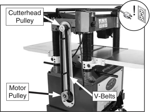
**Figure 50.** Example of belt cover removed to expose V-belts and pulleys.
- Remove front cabinet cover to access motor, as shown in Figure 51.
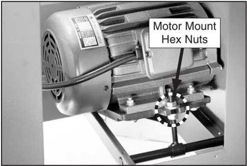
**Figure 51.** Example of front cabinet cover removed to access motor.

-
If V-belts need to be replaced, raise motor to release belt tension (see next step for instructions), roll them off pulleys, then replace with a matched set of 3.
-
To adjust V-belt tension, loosen top motor mount hex nut (see Figure 51 on Page 41), then adjust bottom hex nut to raise or lower motor.
Note: V-belts are correctly tensioned when there is approximately 3/4" deflection when moderate pressure is applied to them midway between pulleys, as illustrated in Figure 52.
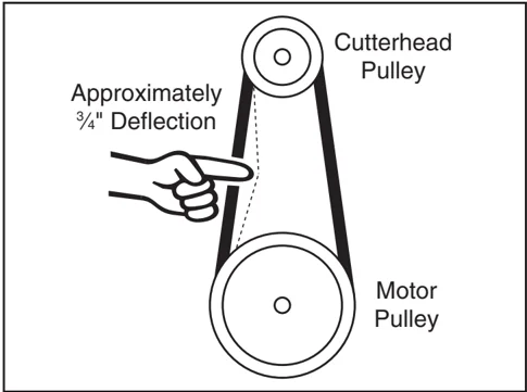
Figure 52. Belt deflection when V-belts are correctly tensioned.
- After V-belts are correctly tensioned, tighten top motor mount hex nut, then re-install cabinet cover and belt cover.
Pulley Alignment
Proper pulley alignment prevents premature V-belt wear and unnecessary load on the motor. The pulleys are properly aligned when they are parallel and in the same plane as each other.
I tems Needed Qty
- Straightedge 3' ........ 1
- Wrench or Socket 14mm, 17mm ........ 2 Ea.
To check/re-align pulleys:
-
DISCONNECT MACHINE FROM POWER!
-
Remove belt cover, then use straightedge to check pulley alignment, as shown in Figure 53.
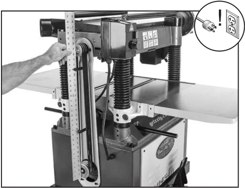
Figure 53. Example of checking pulley alignment.
— If pulleys are parallel and in the same plane, no adjustment is necessary. Re-install belt cover.
— If pulleys are not parallel or in the same plane, remove motor access panel, then proceed to Step 3.
-
Loosen four motor mount bolts, shift motor until pulleys are properly aligned, then re-tighten motor mount bolts.
-
Re-check pulleys and repeat Step 3 as necessary until you are satisfied with pulley alignment, then re-tighten all fasteners, and replace belt cover and motor access panel.
Feed Rollers & Chip Breaker Heights
It is essential that the feed rollers and chip breaker are set at the correct distance below the cutterhead knives at BDC (bottom dead center) to ensure that the workpiece moves through the planer evenly and the correct distance from the cutterhead knives.
To ensure accurate results and make the adjustment process quicker and easier, we recommend using a Rotacator for these adjustments (refer to Accessories).
If a Rotacator is not available, a 6' 2x4 cut into two even sized pieces and a feeler gauge set can be used, but care must be taken when jointing the wood to achieve accurate results.
Dist. Below Knife/Insert at BDC (Figure 54)
- A. Infeed Roller ........ 0.040"
- B. Chip Breaker ........ 0.040"
- C. Outfeed Roller ........ 0.020"
 Figure 54. Planer component recommended clearances (illustration is not to scale).
Using a Rotacator
Items Needed
- Phillips Screwdriver #2 ........ 1
- Hex Wrenches 3mm, 5mm ........ 1 Ea.
- Wrench or Socket 10mm ........ 1 Ea.
- Rotacator (see Page 32) ........ 1
To use a Rotacator:
- DISCONNECT MACHINE FROM POWER!
- Make sure knives are set to correct height (refer to Adjusting/Replacing Knives on Page 28 for detailed instructions). If machine is helical cutterhead, make sure all inserts are properly installed (refer to Rotating/Replacing Cutterhead Inserts on Page 31 for detailed instructions).
- Lower table at least 4" below head casting, then lock it in place.
- Remove dust port, top cover, belt cover, and drive chain cover.
- Using your Rotacator, find bottom dead center (BDC) of any knife/insert edge by slowly rocking cutterhead pulley back and forth, then set Rotacator dial to "0" (see Figure 55).
 Figure 55. Example of using a Rotacator to find BDC.
- Move feed speed knob to neutral position to allow infeed roller to freely rotate.
- Keeping Rotacator dial at "0", position it under right-hand side of infeed roller and find BDC of a serrated edge by rocking infeed roller back and forth.
8. Loosen jam nuts and use set screws on each side of feed roller as shown to adjust height of infeed roller bushing block until Rotacator dial shows 0.040", which is the recommended distance for infeed roller below cutterhead.
 Figure 56. Example of infeed roller bushing block and height adjustment controls.
9. Repeat Steps 7–8 on left side of infeed roller.
10. Re-check both sides of infeed roller and, if necessary, make further adjustments until infeed roller height from side-to-side is 0.040" below BDC of cutterhead knife, then retighten both jam nuts.
11. Keeping same "0" reference on Rotacator dial from Step 5, repeat Steps 7–10 for out-feed roller, but adjust it until it is 0.020" below BDC of cutterhead knife.
12. Using same "0" reference on Rotacator dial from Step 5, perform similar steps as described previously to adjust height of chip breaker to its recommended specification given at beginning of this subsection. The adjustment controls are shown below.
 Figure 57. Example of adjusting chip breaker height.
13. Re-install belt cover, top cover, drive chain cover, and dust port.
-44- G1021X2/G1021Z (Mfd. Since 11/20)
Using Wood Blocks
Items Needed
| Item | Qty |
|---|---|
| Phillips Screwdriver #2 | 1 |
| Hex Wrench 3mm, 5mm | 1 |
| Wrench or Socket 10mm | 1 |
| 2x4 6' Long | 1 |
| Feeler Gauge Set | 1 |
To use wood blocks:
-
Build wood blocks by cutting a straight 6-foot-long 2x4 in half.
Note: Having the wood blocks at an even height is critical to the accuracy of your overall adjustments. For best results, make the 2x4 square with a jointer and table saw before cutting it in half.
-
G1021Z Only: Make sure knives are set to correct height (refer to Adjusting/Replacing Knives on Page 28 for detailed instructions).
-
DISCONNECT MACHINE FROM POWER!
-
Lower bed rollers below table surface (refer to Bed Roller Height on Page 27 for detailed instructions).
-
Place wood blocks along sides of table, as illustrated in Figure 58.
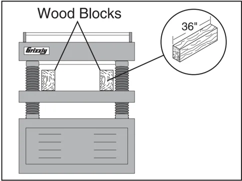
Figure 58. Wood blocks properly positioned on the planer table.
-
Remove dust port, top cover, belt cover, and drive chain cover.
-
Raise table until wood blocks get close to cutterhead.
-
Use belt to rotate cutterhead and continue raising table until blocks just barely touch cutterhead knife/insert at its lowest point of rotation (BDC).
-
Lock table in place. Upward pressure of wood blocks will be holding infeed and outfeed rollers, chip breaker, and pressure bar at same level as knife/insert at BDC.
-
Loosen jam nuts and set screws on each side of infeed roller (see Figure 59).
-
Using a feeler gauge, adjust set screw so it is 0.040" from roller bushing block (see Figure 59), then tighten jam nut. Repeat on other side of infeed roller.
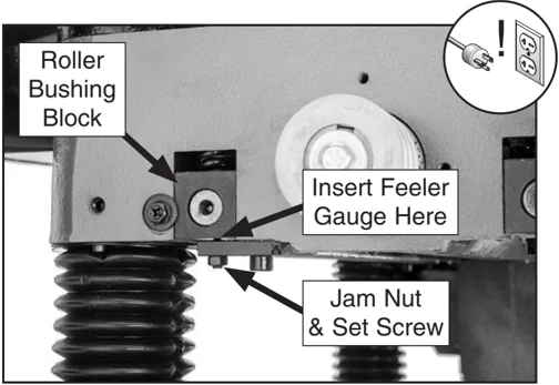
Figure 59. Example of feeler gauge location for adjusting infeed roller height when using wood blocks (one of two locations shown).
- Repeat Steps 10–11 with outfeed roller, only adjust the gaps to 0.020".
G1021X2/G1021Z (Mfd. Since □□/□□) -45-
-
Loosen jam nuts and set screws on each side of chip breaker (see Figure 60).
-
Using a feeler gauge, adjust set screw so it is 0.040" from cross bar (see Figure 60), then tighten jam nut. Repeat on other side of chip breaker.
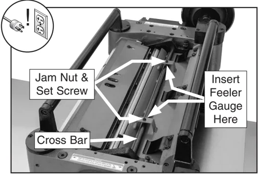
Figure 60. Example of feeler gauge locations for adjusting chip breaker height when using wood blocks.
- Re-install belt cover, top cover, drive chain cover, and dust port.
Adjusting Roller Spring Tension
The infeed and outfeed rollers keep the workpiece moving through the planer. Springs exert downward pressure on the feed rollers while allowing them to raise with an uneven workpiece surface. Proper spring tension is crucial to keep the workpiece moving through the planer during operation.
The ideal feed-roller spring tension varies depending upon the type of wood you plane. When adjusting spring tension, keep the following in mind:
- If you are planing milled lumber with a consistent surface, use less spring tension to reduce the risk of marring the workpiece.
- If you are planing rough lumber with inconsistent surfaces, use greater spring tension to keep the stock moving through the planer.
- If the workpiece consistently stops feeding during operation, the spring tension may need to be increased.
Items Needed \
- Hex Wrench 5mm ........ 1
To adjust feed-roller spring tension:
- DISCONNECT MACHINE FROM POWER!
- Rotate tension screws (shown below) clockwise to increase tension or counterclockwise to decrease tension.
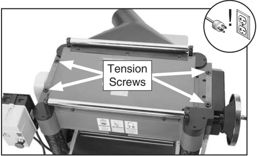
Figure 61. Example of roller spring tension adjustment screws.
-46- G1021X2/G1021Z (Mfd. Since 11/20)
Positioning Chip Deflector
Chip Deflector Gap Setting
If Planer Used w/Dust Collector …………………… 1/4"
If Planer Used w/o Dust Collector ……………… 1/16"
When properly distanced from the cutterhead, the chip deflector directs the chips into the dust hood, and keeps them from falling onto the outfeed roller and being pressed into the workpiece.
Items Needed:
| Item | Qty |
|---|---|
| Wrench or Socket 10mm | 1 |
| Hex Wrench 5mm | 1 |
To adjust chip deflector gap:
- DISCONNECT MACHINE FROM POWER!
- Remove dust hood, top cover, and belt cover.
- Use cutterhead pulley to rotate cutterhead until a knife/insert reaches closest distance to chip deflector (see Figure below), then measure distance between knife/insert and chip deflector.
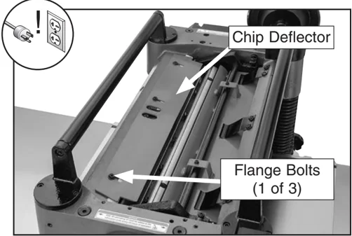
Figure 62. Example of chip deflector and mounting hardware.
- If distance measured in Step 3 is not equal to correct chip deflector gap setting, then loosen flange bolts (see Figure 62) that secure chip deflector and adjust gap to correct setting.
- Re-tighten flange bolts, then replace belt cover, top cover, and dust port.
Calibrating Table Elevation Scale
Although correctly set at the factory, the table elevation scale can be adjusted for accuracy if necessary.
Items Needed
| Item | Qty |
|---|---|
| Phillips Screwdriver #2 | 1 |
| Scrap Piece of Stock | 1 |
| Calipers | 1 |
To calibrate table elevation scale:
- Plane a scrap piece of stock until it is flat and of even thickness along its length.
Note: Turn board over between each pass. - Use calipers to measure board thickness.
- If there is a discrepancy between board thickness and reading on table elevation scale, loosen the screw shown in Figure 63, adjust scale as necessary, then re-tighten screw.
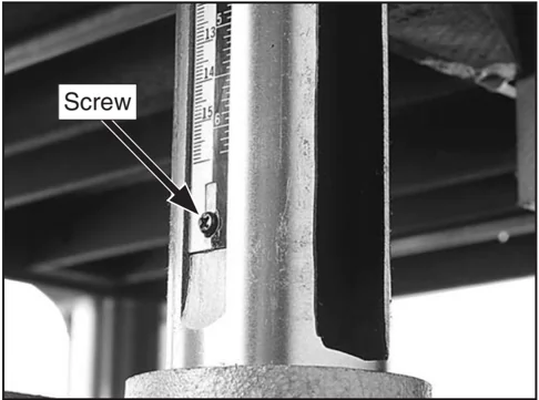
Figure 63. Location of adjustment screw for table elevation scale.
G1021X2/G1021Z (Mfd. Since □□/□□) -47-
Checking Anti-Kickback Fingers
The anti-kickback fingers are an important safety feature of your planer. The fingers hang from a rod suspended across the head casting and in front of the infeed roller, as shown. This design allows the workpiece to easily enter the planer but reduces the risk of kickback by digging into the workpiece if it moves backward.
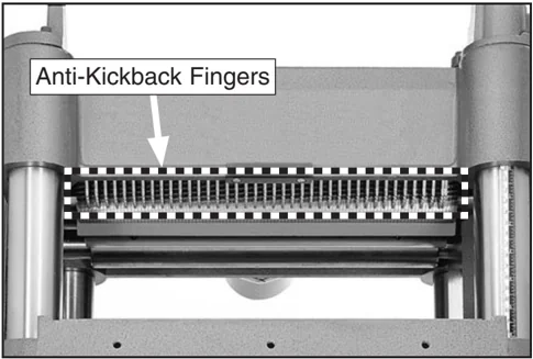
Figure 64. Anti-kickback fingers.
Check the anti-kickback fingers regularly to ensure they swing freely and easily. If the fingers do not swing freely and easily, first clean them with a wood-resin solvent, then inspect them for damage. If any of the fingers are damaged, the device must be replaced before using the machine.
Do not apply oil or other lubricants to the anti-kickback fingers that will attract dust and restrict free movement of the fingers.
WARNING Proper operation of anti-kickback fingers is critical for safe operation of this planer. DO NOT operate planer if anti-kickback fingers are not operating correctly. Failure to heed this warning could result in serious personal injury.
Tensioning Table Height Chain
The table height chain transfers movement from the elevation handwheel to the columns that control table height. The chain drive can be adjusted to remove slack if the chain stretches over time or is loosened during table leveling procedures.
Items Needed Qty
- Phillips Screwdriver #2 ........ 1
- Wrench or Socket 12mm ........ 1
To adjust table height chain tension:
- DISCONNECT MACHINE FROM POWER!
- Remove motor access panel to access table height to chain (see Figure 65).
- Loosen the two chain tension lock bolts, then push idler sprocket against chain with moderate pressure to eliminate slack in chain. While maintaining pressure on idler sprocket, re-tighten lock bolts (see Figure 65).
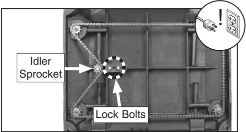
Figure 65. Table height chain adjustment (shown without stand for purpose of illustration).
- Clean and lubricate chain and sprockets (refer to Table Height Chain & Sprockets on Page 36 for detailed instructions), then re-install motor access panel.
NOTICE DO NOT let chain fall off sprockets. It can be very difficult to return chain to its proper location on sprockets without changing table adjustments.
-48- G1021X2/G1021Z (Mfd. Since 11/20)

Adjusting Table Parallelism
Maximum Allowable Tolerances:
- Cutterhead/Table Side-to-Side ........ 0.002"
- Head Casting/Table Front/Back ........ 0.020"
Table parallelism is critical to the operation of the machine. As such, it is essential that the table is parallel with the cutterhead (within 0.002") from side-to-side, as illustrated in Figure 66.
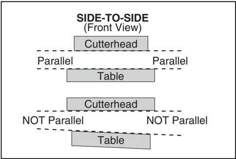
Figure 66. Side-to-side parallelism of table and cutterhead.
How the table sits in relation to the head casting from front-to-back is also important (see Figure 67). Because the feed rollers, pressure bar, and chip breaker will be adjusted off the table position, the tolerances on the front-to-back positioning are not as critical as the cutterhead/table side-to-side positioning. Therefore, the maximum allowable tolerance for the front-to-back parallelism is not more than 0.020".
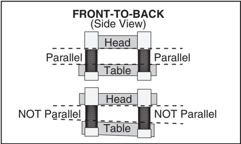
Figure 67. Front-to-back parallelism of table and cutterhead.
Table Parallelism Inspection
Use your Rotacator to inspect the table parallelism. If you do not have a Rotacator, a wood block and feeler gauges may be used, but extra care must be taken to ensure accuracy. If the table is not within the maximum allowable tolerances, it must be adjusted.
Table Parallelism Adjustments
The table is adjusted by turning the chain sprockets underneath the table for movements over 0.008" or by adjusting how the table is mounted on the columns for movements under 0.008".
NOTICE
When making adjustments, tighten fasteners after each step to ensure the accuracy of your tests. When adjusting the chain sprockets, keep in mind that if the chain becomes too loose, it will fall off of all the sprockets, and returning it to its proper location can be extremely difficult.
To adjust table parallelism:
-
DISCONNECT MACHINE FROM POWER!
-
Remove cabinet panel and locate chain on underside of table.
-
Loosen idler sprocket (see Chain Tension instructions on Page 36).
-
Move chain away from sprocket you want to adjust so only that sprocket can be rotated independent of chain.
Note: If the left side of the table is too high, the left two sprockets will need to be adjusted. Each tooth on the sprocket represents .008" of vertical movement as the cogs are turned. Make sure, as you turn the sprockets, to keep an accurate tooth count to ensure that the table is adjusted equally.
-
Mark location of one tooth of sprocket that you are adjusting.
-
Carefully rotate sprocket (clockwise to lower table; counterclockwise to raise table) just enough to position next tooth at marked location, then fit chain around sprocket again.
-
Repeat Steps 4–6 with each sprocket that needs to be adjusted until table-to-cutterhead clearance is within 0.008" from one side to the other.
-
Make sure chain is properly fitted on sprockets, then re-tighten idler sprocket and lock bolts.
-
If necessary, micro-adjust table position by loosening cap screws shown in Figure 68 and raising or lowering table until it is properly aligned with cutterhead.
Note: This process may require adjusting the columns on both the left and right hand sides until you find the correct combination.
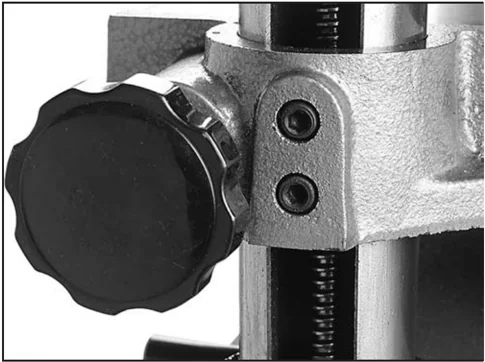
Figure 68. Location of table micro-adjustment screws (one side shown only).
-50- G1021X2/G1021Z (Mfd. Since 11/20)