SECTION 3: SETUP
Needed for Setup
The following items are needed, but not included, for the setup/assembly of this machine.
| Description | Qty |
|---|---|
| Additional People | 1 |
| Safety Glasses | 1 Per Person |
| Forklift (rated for at least 750 lbs.) | 1 |
| Cleaner/Degreaser (Page 17) | As Needed |
| Disposable Shop Rags | As Needed |
| Phillips Screwdriver #2 | 1 |
| Flat Head Screwdriver | 1 |
| Wrench or Socket 12mm, 14mm | 1 Ea. |
| Hex Wrenches 3, 4, 5, 6, 8mm | 1 Ea. |
| Straightedge 4' | 1 |
| Dust-Collection System | 1 |
| 4" Dust Hose (length as needed) | 1 |
| 4" Hose Clamps | 2 |
| Gearbox Oil | As Needed |
Unpacking
This machine was carefully packaged for safe transport. When unpacking, separate all enclosed items from packaging materials and inspect them for shipping damage. If items are damaged, please call us immediately at (570) 546-9663.
IMPORTANT: Save all packaging materials until you are completely satisfied with the machine and have resolved any issues between Grizzly or the shipping agent. You MUST have the original packaging to file a freight claim. It is also extremely helpful if you need to return your machine later.

Inventory
The following is a list of items shipped with your machine. Before beginning setup, lay these items out and inventory them.
If any non-proprietary parts are missing (e.g. a nut or a washer), we will gladly replace them; or for the sake of expediency, replacements can be obtained at your local hardware store.
NOTICE
If you cannot find an item on this list, carefully check around/inside the machine and packaging materials. Often, these items get lost in packaging materials while unpacking or they are pre-installed at the factory.
Box 1 (Figure 5)
- A. Planer Unit (Not Shown) ........ 1
- B. Cast-Iron Extension Tables ........ 2
- C. Table Elevation Handwheel ........ 1
- D. Dust Port ........ 1
Tools and Hardware (Figure 6)
- E. Hex Wrenches 3, 4, 6mm ........ 1 Ea.
- F. Hex Bolts M8-1.25 x 25 (Ext. Tables) ........ 6
- G. Set Screws M8-1.25 x 12 (Ext. Tables) ........ 6
- H. Flange Bolts M6-1 x 12 (Dust Port) ........ 6 I. LOW/HIGH Direction Label (Handwheel)... 1
- J. Hex Nut M10-1.25 (Handwheel) ........ 1
- K. Key 4 x 4 x 10 (Handwheel) ........ 1
- L. Flat Washers 8mm (Ext. Tables) ........ 6
- M. Flat Washers 10mm (Handwheel) ........ 1
- N. Handwheel Handle (Handwheel) ........ 1 O. Open-End Wrenches 10/13, 12/14mm..1 Ea.
G1021X2 Only (Figure 7)
- P. T-Handle Torx Drivers T-25 ........ 2
- Q. Flat Head Torx Screws #10-32 x 1/2" ........ 10
- R. Indexable Carbide Inserts 15 x 15 x 2.5 ........ 5
G1021Z Only (Figure 8)
- S. Knife-Setting Jig ........ 1
- —E-Clips 9mm ........ 4
- —Jig Feet ........ 2
- —Jig Shaft ........ 1
 Figure 5. Box inventory.
 Figure 6. Tools and hardware.
 Figure 7. Tools and hardware (G1021X2 only).
 Figure 8. Tools and hardware (G1021Z only).
Cleanup
The unpainted surfaces of your machine are coated with a heavy-duty rust preventative that prevents corrosion during shipment and storage. This rust preventative works extremely well, but it will take a little time to clean.
Be patient and do a thorough job cleaning your machine. The time you spend doing this now will give you a better appreciation for the proper care of your machine's unpainted surfaces.
There are many ways to remove this rust preventative, but the following steps work well in a wide variety of situations. Always follow the manufacturer's instructions with any cleaning product you use and make sure you work in a well-ventilated area to minimize exposure to toxic fumes.
Before cleaning, gather the following:
- Disposable rags
- Cleaner/degreaser (WD•40 works well)
- Safety glasses & disposable gloves
- Plastic paint scraper (optional)
Basic steps for removing rust preventative:
- Put on safety glasses.
- Coat the rust preventative with a liberal amount of cleaner/degreaser, then let it soak for 5–10 minutes.
- Wipe off the surfaces. If your cleaner/degreaser is effective, the rust preventative will wipe off easily. If you have a plastic paint scraper, scrape off as much as you can first, then wipe off the rest with the rag.
- Repeat Steps 2–3 as necessary until clean, then coat all unpainted surfaces with a quality metal protectant to prevent rust.
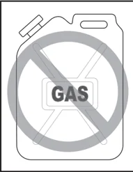
Gasoline and petroleum products have low flash points and can explode or cause fire if used to clean machinery. Avoid using these products to clean machinery.
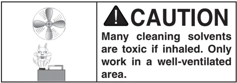
Many cleaning solvents are toxic if inhaled. Only work in a well-ventilated area.
NOTICE
Avoid harsh solvents like acetone or brake parts cleaner that may damage painted surfaces. Always test on a small, inconspicuous location first.
T23692—Orange Power Degreaser A great product for removing the waxy shipping grease from the non-painted parts of the machine during clean up.

Figure 9. T23692 Orange Power Degreaser.
Site Considerations
Weight Load
Refer to the Machine Data Sheet for the weight of your machine. Make sure that the surface upon which the machine is placed will bear the weight of the machine, additional equipment that may be installed on the machine, and the heaviest workpiece that will be used. Additionally, consider the weight of the operator and any dynamic loading that may occur when operating the machine.
Space Allocation
Consider the largest size of workpiece that will be processed through this machine and provide enough space around the machine for adequate operator material handling or the installation of auxiliary equipment. With permanent installations, leave enough space around the machine to open or remove doors/covers as required by the maintenance and service described in this manual. See below for required space allocation.
CAUTION
Children or untrained people may be seriously injured by this machine. Only install in an access restricted location.
Physical Environment
The physical environment where the machine is operated is important for safe operation and longevity of machine components. For best results, operate this machine in a dry environment that is free from excessive moisture, hazardous chemicals, airborne abrasives, or extreme conditions. Extreme conditions for this type of machinery are generally those where the ambient temperature range exceeds 41°–104°F; the relative humidity range exceeds 20%–95% (non-condensing); or the environment is subject to vibration, shocks, or bumps.
Electrical Installation
Place this machine near an existing power source. Make sure all power cords are protected from traffic, material handling, moisture, chemicals, or other hazards. Make sure to leave enough space around machine to disconnect power supply or apply a lockout/tagout device, if required.
Lighting
Lighting around the machine must be adequate enough that operations can be performed safely. Shadows, glare, or strobe effects that may distract or impede the operator must be eliminated.
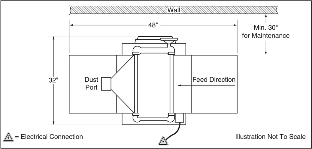
= Electrical Connection Illustration Not To Scale
Figure 10. Minimum working clearances for Models G1021Z and G1021X2.
-18- G1021X2/G1021Z (Mfd. Since 11/20)
Lifting & Placing
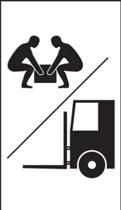
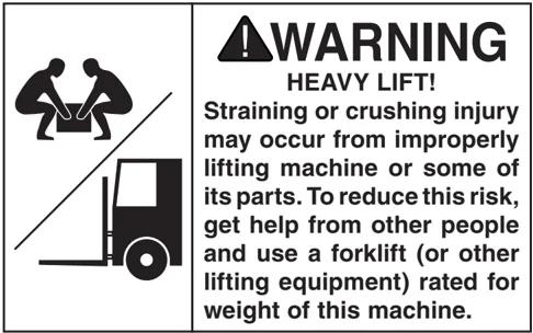
WARNING HEAVY LIFT! Straining or crushing injury may occur from improperly lifting machine or some of its parts. To reduce this risk, get help from other people and use a forklift (or other lifting equipment) rated for weight of this machine.
The planer is equipped with four lifting bars that extend in order to lift and place the planer.
To lift and place the planer, extend the lifting bars and use a forklift to lift the machine off the pallet, as shown in Figure 11, then set the planer down in a suitable location and return the lifting bars to their original position.
Tip: When positioning lift forks, place shop rags or cardboard between forks and cabinet stand to avoid scratching paint.
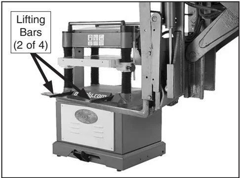
Figure 11. Example of lifting planer with forklift.
Assembly
The machine must be fully assembled before it can be operated. Before beginning the assembly process, refer to Needed for Setup and gather all listed items. To ensure the assembly process goes smoothly, first clean any parts that are covered or coated in heavy-duty rust preventative (if applicable).
To assemble planer:
-
Attach each cast-iron extension table to planer table with (3) M8-1.25 x 25 hex bolts and (3) 8mm flat washers. Do not fully tighten hex bolts at this time.
-
Thread (3) M8-1.25 x 12 set screws into each extension table at locations shown in Figure 12.
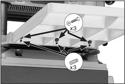
Figure 12. Extension table mounting locations.
- Using a straightedge as a guide, rotate set screws until extension tables are in plane with main table, then fully tighten hex bolts installed during Step 1 on Page 19.
Note: Bed rollers will give you a false reading with your straightedge if they are raised above table. Move them down or work around them when leveling extension wings (refer to Bed Roller Height on Page 27 for details).
-
Insert key into keyway on handwheel shaft on top of planer.
-
Line up notch in handwheel bore with key, then slide handwheel onto shaft.
-
Slide LOW/HIGH direction label onto handwheel shaft, and secure handwheel with 10mm flat washer and M10-1.25 hex nut (see Figure 13).
-
Thread handwheel handle into handwheel (see Figure 13), and tighten with wrench.
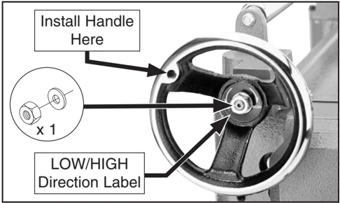
Figure 13. Table elevation handwheel installed.
- Attach dust port to planer with (6) M6-1 x 12 flange bolts (see Figure 14).
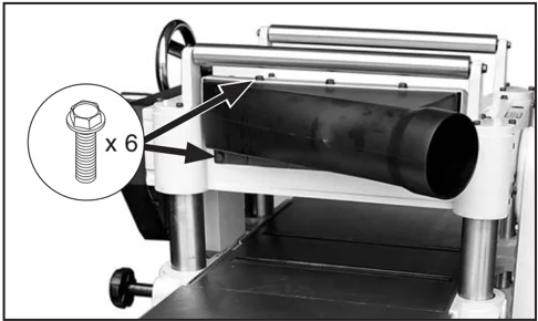
Figure 14. Dust port installed.
- G1021Z Only: Assemble knife-setting jig using knife-setting shaft, feet, and 9mm E-clips, as shown in Figure 15.
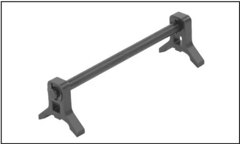
Figure 15. Knife-setting jig assembled.
Dust Collection
CAUTION
This machine creates a lot of wood chips/ dust during operation. Breathing airborne dust on a regular basis can result in perma- nent respiratory illness. Reduce your risk by wearing a respirator and capturing the dust with a dust-collection system.
Minimum CFM at Dust Port: 400 CFM Do not confuse this CFM recommendation with the rating of the dust collector. To determine the CFM at the dust port, you must consider these variables: (1) CFM rating of the dust collector, (2) hose type and length between the dust col- lector and the machine, (3) number of branches or wyes, and (4) amount of other open lines throughout the system. Explaining how to cal- culate these variables is beyond the scope of this manual. Consult an expert or purchase a good dust-collection "how-to" book.
To connect the machine to a dust-collection sys- tem, fit a 4" dust hose over the dust port, and secure in place with a hose clamp (see Figure 16). Tug the hose to make sure it does not come off.
Note: A tight fit is necessary for proper performance.
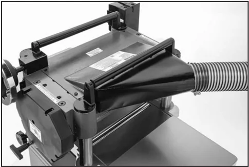
Figure 16. Example of dust hose connected to dust port.
Checking Gearbox Oil Level
Before starting your machine for the first time, check the gearbox oil level. The proper oil level is just even with the bottom of the fill plug hole. The gearbox uses ISO 320, SAE 140 gear oil, or SAE 85W–140 multi-weight gear oil. DO NOT mix oil types.
Note: For easier access to the fill plug, remove the drive chain cover (see Figure 17).
To check gearbox oil level:
- Remove gearbox fill plug (see Figure 17).
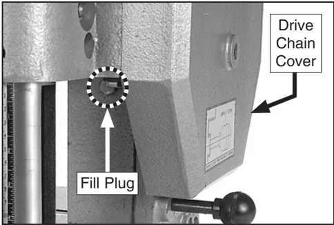
Figure 17. Location of gearbox fill plug.
- Dip short end of a clean 6mm hex wrench inside fill hole, and then remove it. — If the end of the hex wrench is coated with oil, then the gearbox oil level is okay. Replace the fill plug and continue setup. — If the end of the hex wrench is not coated with oil, then you need to add more oil. Refer to Gearbox Oil on Page 37 for instructions on how to do this.
Note: We recommend that you replace the gearbox oil after the first 20 hours of operation. This is a normal break-in procedure and will help maximize the service life of the machine by flushing away any particles from the break-in and manufacturing process.
Test Run
Once assembly is complete, test run the machine to ensure it is properly connected to power and safety components are functioning correctly.
If you find an unusual problem during the test run, immediately stop the machine, disconnect it from power, and fix the problem BEFORE operating the machine again. The Troubleshooting table in the SERVICE section of this manual can help.
The Test Run consists of verifying the following:
- The motor powers up and runs correctly, and
- the STOP/reset button safety feature functions properly.
!WARNING Serious injury or death can result from using this machine BEFORE understanding its controls and related safety information. DO NOT operate, or allow others to operate, machine until the information is understood.
!WARNING DO NOT start machine until all preceding setup instructions have been performed. Operating an improperly set up machine may result in malfunction or unexpected results that can lead to serious injury, death, or machine/property damage.
To test run machine:
- Clear all setup tools and loose objects away from machine.
- Push STOP button in.
- Connect machine to power supply.
- Twist STOP button clockwise until it springs out (see Figure 18). This resets the switch so the machine can start.

Figure 18. Resetting the switch.
- Press START button to turn machine ON. Verify motor starts up and runs smoothly without any unusual problems or noises.
- Press STOP button to turn machine OFF.
- WITHOUT resetting STOP button, try to start machine by pressing the START button. The machine should not start.
— If the machine does not start, the STOP button safety feature is working correctly. Congratulations! Test Run is complete.
— If the machine does start with the STOP button pushed in, immediately disconnect power to the machine. The STOP button safety feature is not working correctly and must be replaced before further using the machine. Call Tech Support for help.
Recommended Adjustments
The adjustments listed below have been performed at the factory. However, because of the many variables involved with shipping, we recommend that you verify the adjustments to ensure the best possible results from your new machine.
Step-by-step instructions for these adjustments can be found in the SERVICE section starting on Page 38.
Factory adjustments that should be verified:
- Tensioning/replacing V-belts (Page 41).
- Calibrating table elevation scale (Page 47).
- Pulley alignment (Page 42).
NOTICE
After approximately 16 hours of operation, V-belts will stretch and seat into pulley grooves and need to be properly tensioned to avoid severely reducing life of V-belts. Refer to Tensioning/Replacing V-Belts on Page 41 for detailed instructions.
SECTION 4: OPERATIONS
Operation Overview
The purpose of this overview is to provide the novice machine operator with a basic understanding of how the machine is used during operation, so the machine controls/components discussed later in this manual are easier to understand.
Due to the generic nature of this overview, it is not intended to be an instructional guide. To learn more about specific operations, read this entire manual, seek additional training from experienced machine operators, and do additional research outside of this manual by reading "how-to" books, trade magazines, or websites.

WARNING To reduce your risk of serious injury, read this entire manual BEFORE using machine.
WARNING Eye injuries, respiratory problems, or hearing loss can occur while operating this tool. Wear personal protective equipment to reduce your risk from these hazards.
NOTICE If you are not experienced with this type of machine, WE STRONGLY RECOMMEND that you seek additional training outside of this manual. Read books/magazines or get formal training before beginning any projects. Regardless of the content in this section, Grizzly Industrial will not be held liable for accidents caused by lack of training.
To complete a typical operation, the operator does the following:
- Examines workpiece to make sure it is suitable for planing.
- Puts on safety glasses or face shield, a respirator, and hearing protection.
- Places workpiece on table with flat side down and correctly adjusts table height for workpiece thickness and depth of cut. — If workpiece is bowed, operator surface planes workpiece on a jointer until one side is flat. Doing so ensures that it sits solidly on planer table during operation.
- When all safety precautions have been taken, turns planer ON.
- Stands to one side of planer path to reduce risk of kickback injuries, then feeds workpiece into planer until infeed roller grabs it.
Note: Infeed and outfeed rollers control feed rate of workpiece as it passes through planer. Operator should not push or pull on workpiece.
— If cut is too deep and bogs down planer, operator immediately reduces depth of cut. 6. Once workpiece is clear of outfeed roller and stops moving, operator removes workpiece from outfeed table and measures workpiece thickness. If further planing is required, operator raises table slightly (approximately 1/4 to 1/2 turn of table height handwheel), then feeds workpiece into front of planer again. 7. Operator continues process until desired thickness is achieved, then turns machine OFF.


Workpiece Inspection
Some workpieces are not safe to use or may require modification before they are. Before cutting, inspect all workpieces for the following:
-
Material Type: This machine is only intended for workpieces of natural wood fiber. Attempting to use workpieces of any other material that may break apart during operation could lead to serious personal injury and property damage.
-
Foreign Objects: Inspect lumber for defects and foreign objects (nails, staples, embedded gravel, etc.). If you have any question about the quality of your lumber, DO NOT use it. Remember, wood stacked on a concrete floor can have small pieces of stone or concrete pressed into the surface.
-
Large/Loose Knots: Loose knots can become dislodged during operation. Large knots can cause kickback and machine damage. Always use workpieces that do not have large/loose knots.
-
Wet or "Green" Stock: Avoid using wood with a high water content. Wood with more than 20% moisture content or wood exposed to excessive moisture (such as rain or snow), will cut poorly and cause excessive wear to the machine. Excess moisture can also hasten rust and corrosion of the machine and/or individual components.
-
Excessive Warping: Workpieces with excessive cupping, bowing, or twisting are dangerous to cut because they are unstable and often unpredictable when being cut. DO NOT use workpieces with these characteristics!
-
Minor Cupping: Workpieces with slight cupping can be safely supported if the cupped side is facing the table. On the contrary, a workpiece supported on the bowed side will rock during operation and could cause severe injury from kickback.
Wood Types
The species of wood, as well as its condition, greatly affects the depth of cut the planer can effectively take with each pass.
The chart in the figure below shows the Janka Hardness Rating for a number of commonly used species. The larger the number, the harder the workpiece, and the less material should be removed in any one pass for good results.
Note: The Janka Hardness Rating is expressed in pounds of force required to embed a 0.444" steel ball into the surface of the wood to a depth equal to half the ball's diameter.
| Species | Janka Hardness |
|---|---|
| Ebony | 3220 |
| Red Mahogany | 2697 |
| Rosewood | 1780 |
| Red Pine | 1630 |
| Sugar Maple | 1450 |
| White Oak | 1360 |
| White Ash | 1320 |
| American Beech | 1300 |
| Red Oak | 1290 |
| Black Walnut | 1010 |
| Teak | 1000 |
| Black Cherry | 950 |
| Cedar | 900 |
| Sycamore | 770 |
| Douglas Fir | 660 |
| Chestnut | 540 |
| Hemlock | 500 |
| White Pine | 420 |
| Basswood | 410 |
| Eastern White Pine | 380 |
| Balsa | 100 |
Figure 19. Janka Hardness Rating for some common wood species.
-24-
Planing Tips
- Inspect your lumber for twisting or cupping, and surface one face on a jointer if necessary before planing workpiece.
- Scrape off all glue when planing glued-up panels. Dried glue can quickly dull knives/inserts.
- DO NOT plane more than one piece at a time. Never plane multiple pieces side by side.
- Never remove more than the recommended amount of material on each pass. Only remove a small amount of material on each pass when planing wide or dense stock.
- Support the workpiece on both ends. Get assistance from another person if you are planing long lumber, or use roller stands to support the workpiece.
- Measure the workpiece thickness with calipers to get exact results.
- Carefully inspect all stock to make sure it is free of large knots or foreign objects that may damage your knives/inserts, cause kickback, or be ejected from the planer.
- When possible, plane equal amounts on each side of the board to reduce the chance of twisting or cupping.
- Use the entire width of the planer to wear knives/inserts evenly. With narrow workpieces, alternate between far left, far right, and the middle of the table. Your knives/inserts will remain sharp much longer.
- To avoid "chip marks," always plane WITH the grain direction of the wood. Never plane cross-grain or end-grain.
- Plane ONLY natural wood fiber. Do not plane wood composites or other materials that could break up in the planer and cause operator injury or damage to planer.
- Always true cupped or warped stock on a jointer before planing.
Cutting Problems
Below is a list of wood characteristics you may encounter when planing. The following descriptions of defects will give you some possible answers to problems you may encounter while planing different materials. Possible solutions follow the descriptions.
Chipped Grain
Problem: Usually a result of cutting against the grain, planing lumber with knots or excessive amount of cross grain, or using dull knives/inserts.
Note: Some amount of chipping is normal with highly figured wood.
Solution: Decrease the depth of cut. Reduce the feed rate. Inspect your lumber and determine if its grain pattern is causing the problem. If the lumber does not show substantial crossgrain, inspect your knives/inserts.
Fuzzy Grain
Problem: Usually caused by surfacing lumber with too high of a moisture content. Sometimes fuzzy grain is an unavoidable characteristic of some woods, such as basswood. Fuzzy grain can also be caused by dull knives/inserts.
Solution: Check the lumber with a moisture meter. If moisture is greater than 20%, sticker the lumber and allow it to dry. Otherwise, inspect the knife/insert condition.
Snipe
Problem: Occurs when board ends have more material removed than the rest of the board. Usually caused when the workpiece is not properly supported as it goes through the machine. In many cases, however, a small amount of snipe is inevitable.
Solution: Hold workpiece up slightly as it leaves the outfeed end of the planer. The best way to deal with snipe is by planing lumber longer than your intended work length and then cutting off the excess after planing is completed.
Pitch & Glue Build-up
Problem: Glue and resin buildup on the rollers and cutterhead will cause overheating by decreasing cutting sharpness while increasing drag in the feed mechanism. The result can include scorched lumber, uneven knife/insert marks, and chatter.
Solution: Clean the rollers and cutterhead.
Chip Marks or Indentations
Problem: Chip indentation or chip bruising is the result of wood chips not being thrown away from the cutterhead and out of the machine. Instead they are carried around the cutterhead, deposited on the planed surface and crushed by the outfeed roller. Some of the causes of chip indentation are:
- Wood chips/sawdust not being properly expelled from the cutterhead.
- The type of lumber being planed. Certain species have a tendency to chip bruise.
- A high moisture content (over 20%) or surface moisture (refer to Workpiece Inspection).
- Dull knives/inserts.
- Excessive depth of cut.
Solution:
- Use a proper dust-collection system; adjust chip deflector in or out as necessary.
- Lumber must be completely dry, preferably kiln-dried (KD). Air-dried (AD) lumber must be seasoned properly and have no surface moisture. DO NOT surface partially-air-dried (PAD) lumber.
- Make sure planer knives/inserts are sharp.
- Reduce depth of cut.
Rippled Cut
Problem: Regularly spaced indentations across face of workpiece are caused by excessive out-feed roller pressure or excessive feed rate.
Solution: Reduce outfeed roller pressure; reduce feed rate.
Depth of Cut
Table Movement per Handwheel Revolution
- One Full Revolution ........ 2mm (0.08")
Material Thickness Range
- Minimum–Maximum Stock Thickness ........ 3/16"–6"
The depth of cut on a planer means the amount of material that is removed from the top of the workpiece as it passes underneath the cutterhead.
The depth of cut is set by adjusting the distance of the table below the cutterhead. This distance is the thickness of the workpiece minus the depth of cut. The planing depth of cut is controlled by using the table elevation handwheel on the right side of the machine. Rotating the handwheel clockwise raises the table.
Although the correct depth of cut varies according to wood hardness and workpiece width, we recommend the maximum depth of cut (per pass) be no more than 1/16". A series of light cuts will give better end results and put less stress on the planer than trying to take off too much material in a single pass.
The depth of cut can be referenced directly from the inch/millimeter scale on the front of the planer, as shown.
Note: The scale functions as a general guide only, and is not intended for low-tolerance, precision results.
 Figure 20. Location of depth-of-cut controls (G1021X2 shown).
-26-
Bed Roller Height
- Bed Roller Height Range ........ 0.002"–0.020"
The correct height of the bed rollers will vary, depending on the type of material you intend to plane. However, as a general rule, keep the bed roller height within 0.002"–0.020" above the table surface, as illustrated in Figure 21.
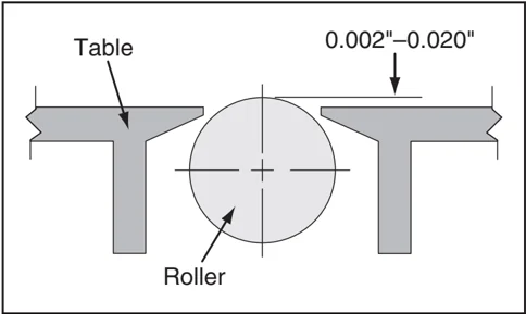
Figure 21. Recommended bed roller height above the table surface.
When planing rough stock, set the rollers high to keep the lumber from dragging along the bed. When planing milled lumber, set the rollers low to help minimize snipe.
To ensure accurate results and make the adjustment process quicker and easier, we recommend using a Rotacator (refer to Page 32) to gauge the bed roller height from the table surface. If a Rotacator is not available, a straightedge and feeler gauges can be used, but care must be taken to achieve accurate results.
NOTICE
Bed rollers that are not adjusted to the correct height or out of alignment with each other can cause poor finishes, inconsistent planing thickness, and other undesirable results.
Items Needed Qty
- Hex Wrench 3mm ........ 1
- Open-End Wrench 12mm ........ 1
- Straightedge ........ 1
- Feeler Gauge Set ........ 1
- Rotacator (optional, Page 32) ........ 1
To adjust bed rollers:
- DISCONNECT MACHINE FROM POWER!
- Completely lower table to give yourself enough room to work.
- Loosen set screws (see Figure 22) above each of four roller adjustment cams (there are two on each side of planer).
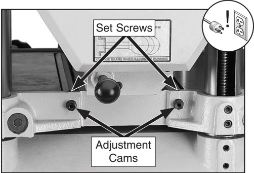
Figure 22. Bed roller height controls (G1021X2 shown).
- Rotate eccentric adjustment cams to raise or lower bed rollers to desired height above table surface.
- Verify both sides of each roller are at the same height, then re-tighten set screws to secure in place.
- Re-check roller heights to make sure they did not change while being secured.
— If roller heights are not correct, repeat this procedure until they are.
Setting Feed Rate
- High Feed Rate ........ 28 FPM
- Low Feed Rate ........ 16 FPM
The infeed and outfeed rollers move the work-piece through the planer while keeping it flat and providing a consistent rate of movement. The speed that these rollers move the workpiece through the planer is the feed rate.
Generally, low feed rates are used for finishing passes, while higher feed rates are used for dimensioning passes.
The figure below illustrates the three different positions of the feed rate control knob:
- Push knob in to use high feed rate.
- Pull the knob out to use the low feed rate.
- Move knob to center position to place gear-box in neutral.
 Figure 23. Feed rate control knob positions.
NOTICE Only change the feed rate when the planer is running, but DO NOT attempt to change the feed rate during any cutting operations or damage to the gearbox will result.
Adjusting/Replacing Knives (G1021Z)
! WARNING To reduce risk of shock or accidental startup, always disconnect machine from power before adjustments, maintenance, or service.
CAUTION Cutterhead knives are extremely sharp. Accidental contact with knives can result in severe cuts. Take great caution whenever working with or around cutterhead knives. Wear heavy leather gloves to reduce risk of severe cuts.
NOTICE To maintain accurate and consistent planing results, we do not recommend sharpening knives yourself. Instead, just replace dull knives or have them professionally sharpened.
Setting the height of the knives correctly is crucial to the proper operation of your planer and is very important in keeping the knives sharp. If one knife protrudes higher than the others, it will do the majority of the work, dull much faster, and produce poor cutting results.
The knife-setting jig included with this planer is designed to set the knives at a uniform distance of 0.070" above the cutterhead surface.
Note: If you need to replace or sharpen a knife, you can remove the knife from the cutter-head during Step 4 of the following procedure. Thoroughly clean out any debris from the knife slots before replacing the knives.
Replacement knives are available through Grizzly (refer to Accessories for options).
-28-
Items Needed
| Item | Qty |
|---|---|
| Phillips Screwdriver #2 | 1 |
| Wrench or Socket 12mm, 13mm | 1 Ea. |
| Hex Wrench 3mm | 1 |
| Knife-Setting Jig | 1 |
| Heavy Leather Gloves | 1 Pair |
To adjust height of knives:
- DISCONNECT MACHINE FROM POWER!
- Remove dust hood and top cover to expose cutterhead.
- Put on heavy leather gloves.
- Remove belt cover, then rotate cutterhead pulley to provide access to one of the knives.
Note for G1021Z Only: The cutterhead for Model G1021Z ships with both springs and jack screws to adjust the knife height (see Figure 24)—which one you use is up to your personal preference. However, if you use the springs, you must first remove the jack screws from the cutterhead before proceeding.
— The advantage of using springs is that springs maintain a constant upward pressure on the knives while using the knife-setting Jig during Step 6.
— The advantage of using jack screws is that once you set the proper height of the screws, they should require little to no adjustment when replacing the knives.
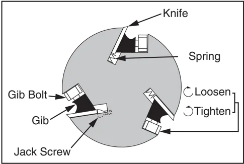
Figure 24. G1021Z cutterhead components.
- Loosen cutterhead gib bolts until knife is completely loose.
— If you are replacing the knives, remove the old knife and install the new one, making sure the beveled edge of the new knife is facing the correct direction.
- Position knife-setting jig over knife so that knife edge is directly under center pad, as shown below.
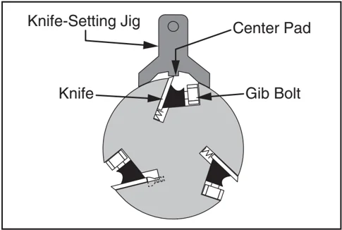
Figure 25. Knife-setting jig correctly positioned over knife.
G1021X2/G1021Z (Mfd. Since □□/□□) -29-
- Jack Screws: Insert hex wrench into access holes in cutterhead (see Figure 26), and rotate jack screws to raise or lower knife until it barely touches center pad of knife-setting jig with all legs of jig still firmly on cutterhead, then snug gib bolts enough to hold knife in place without fully tightening gib bolts (see Figure 27).
Springs: Insert hex wrench into access holes in cutterhead (see Figure 26), and remove jack screws. Push down on knife jig until all legs of jig are firmly on cutterhead and knife just touches center pad of jig, then tighten gib bolts enough to hold knife in place without fully tightening gib bolts (see Figure 27).
 Figure 26. Example of jack screw access holes in cutterhead.
 Figure 27. Using knife-setting jig to set knife height on Model G1021Z.
- Incrementally snug gib bolts in an even manner, starting at middle and working your way to ends by alternating left and right, as illustrated.
 Figure 28. Gib bolt tightening sequence.
-
Repeat Step 8, snugging gib bolts a little more.
-
Repeat Step 8, this time fully tightening all gib bolts.
-
Repeat Steps 4–8 for remaining knives.
Rotating/Replacing Cutterhead Inserts (G1021X2)
The helical cutterhead is equipped with indexable carbide inserts that can be rotated to reveal any one of their four cutting edges. If one edge of the insert becomes dull or damaged, simply rotate it 90° to reveal a fresh cutting edge, as shown in Figure 29.
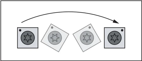
Figure 29. Insert rotating sequence.
Items Needed
| Item | Qty |
|---|---|
| Phillips Screwdriver #2 | 1 |
| Wrench or Socket 12mm, 13mm | 1 |
| Torque Wrench | 1 |
| T-20 Torx Bit | 1 |
| Heavy Leather Gloves | 1 Pair |
| Light Machine Oil | As Needed |
To rotate or replace a helical cutterhead insert:
- DISCONNECT MACHINE FROM POWER!
- Remove dust port, top cover, and belt cover.
- Put on heavy leather gloves to protect your fingers and hands.
CAUTION
The carbide inserts are very sharp and can quickly cut your hands. ALWAYS use caution and heavy leather gloves when handling these parts to reduce the risk of personal injury.
- Remove any sawdust or debris from head of insert, Torx screw, and surrounding area (see Figure 30).
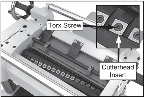
Figure 30. G1021X2 cutterhead inserts and Torx screws.
- Remove Torx screw and insert, then clean all dust and debris from both parts and pocket they were removed from.
Note: Proper cleaning of insert, Torx screw, and cutterhead pocket is critical to achieving a smooth finish. Dirt or dust trapped between insert and cutterhead will raise insert, and make marks on your workpiece when planing.
Tip: Use low-pressure compressed air or a vacuum nozzle to clean out cutterhead pocket.
- Rotate insert 90° and install so that a fresh cutting edge faces outward (see Figure 29).
— When all four insert cutting edges have been used, replace insert with a new one. Always position insert reference dot in same position when installing a new insert to aid in rotational sequencing.
- Lubricate Torx screw threads with a very small amount of light machine oil, wipe excess off, and torque screw to 50–55 inch/pounds.
Note: If too much oil is applied to the threads, excess oil will attempt to squeeze out of the threaded hole and raise insert during installation, bringing it out of height alignment.
