Grizzly
Industrial, Inc.
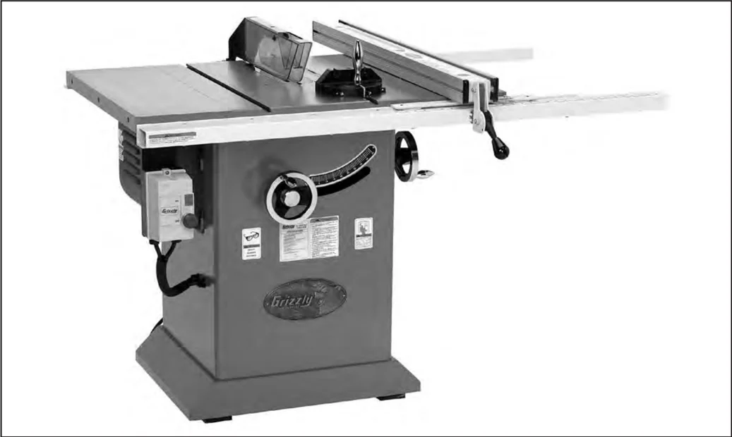
MODEL G0478
10" Hybrid Table Saw
OWNER'S MANUAL
COPYRIGHT © SEPTEMBER, 2005 BY GRIZZLY INDUSTRIAL, INC. REVISED DECEMBER, 2017 (HE) WARNING: NO PORTION OF THIS MANUAL MAY BE REPRODUCED IN ANY SHAPE OR FORM WITHOUT THE WRITTEN APPROVAL OF GRIZZLY INDUSTRIAL, INC. #EW7460 PRINTED IN TAIWAN

WARNING!
Some dust created by power sanding, sawing, grinding, drilling, and other construction activities contains chemicals known to the State of California to cause cancer, birth defects or other reproductive harm. Some examples of these chemical are:
- Lead from lead-based paints.
- Crystalline silica from bricks, cement and other masonry products.
- Arsenic and chromium from chemically-treated lumber.
Your risk from these exposures varies, depending on how often you do this type of work. To reduce your exposure to these chemicals: Work in a well ventilated area, and work with approved safety equipment, such as those dust masks that are specially designed to filter out microscopic particles.

Table of Contents
- INTRODUCTION ........ 3
- Foreword ........ 3
- Contact Info ........ 3
- Machine Data Sheet ........ 4
- Identification ........ 5
- SECTION 1: SAFETY ........ 6
- Safety Instructions for Machinery ........ 6
- Additional Safety Instructions for Table Saws ........ 8
- Preventing Kickback ........ 9
- Protecting Yourself From Kickback ........ 9
- Glossary Of Terms ........ 10
- SECTION 2: CIRCUIT REQUIREMENTS ........ 11
- 110/220V Operation ........ 11
- Grounding ........ 12
- Extension Cords ........ 12
- SECTION 3: SET UP ........ 13
- Set Up Safety ........ 13
- Items Needed For Set Up ........ 13
- Unpacking ........ 13
- Inventory ........ 14
- Hardware Recognition Chart ........ 15
- Clean Up ........ 16
- Site Considerations ........ 16
- Extension Wings ........ 17
- Fence ........ 17
- Switch ........ 18
- Handwheels ........ 18
- Blade ........ 19
- Table Insert ........ 19
- Blade Guard ........ 20
- Recommended Adjustments ........ 21
- Test Run ........ 22
- SECTION 4: OPERATIONS ........ 23
- Operation Safety ........ 23
- Blade Selection ........ 23
- Non-Through and Through Cuts ........ 25
- Ripping ........ 25
- Crosscutting ........ 26
- Miter Cuts ........ 27
- Blade Tilt/Bevel Cuts ........ 27
- Dado Cutting ........ 28
- Rabbet Cutting ........ 30
- Resawing ........ 32
- SECTION 5: ACCESSORIES ........ 35
- SECTION 6: MAINTENANCE ........ 39
- Schedule ........ 39
- Cleaning ........ 39
- Lubrication ........ 39
- Maintenance Log ........ 40
- SECTION 7: SERVICE ........ 41
- Troubleshooting ........ 41
- Replacing Flat Belt ........ 43
- Blade Parallelism ........ 44
- 45° & 90° Stops ........ 46
- G0478 110/220V Wiring Diagram ........ 47
- Electrical Components ........ 48
- Parts Breakdown ........ 49
- Parts Breakdown ........ 50
- Safety Labels ........ 51
- Parts List ........ 52
- Parts List ........ 53
- WARRANTY AND RETURNS ........ 54
INTRODUCTION
Foreword
We are proud to provide a high-quality owner’s manual with your new machine!
We made every effort to be exact with the instructions, specifications, drawings, and photographs in this manual. Sometimes we make mistakes, but our policy of continuous improvement also means that sometimes the machine you receive is slightly different than shown in the manual.
If you find this to be the case, and the difference between the manual and machine leaves you confused or unsure about something, check our website for an updated version. We post current manuals and manual updates for free on our website at www.grizzly.com.
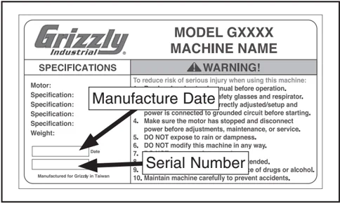
Alternatively, you can call our Technical Support for help. Before calling, make sure you write down the Manufacture Date and Serial Number from the machine ID label (see below). This information is required for us to provide proper tech support, and it helps us determine if updated documentation is available for your machine.
Contact Info
We stand behind our machines! If you have questions or need help, contact us with the information below. Before contacting, make sure you get the serial number and manufacture date from the machine ID label. This will help us help you faster.
Grizzly Technical Support 1815 W. Battlefield Springfield, MO 65807 Phone: (570) 546-9663 Email: techsupport@grizzly.com
We want your feedback on this manual. What did you like about it? Where could it be improved? Please take a few minutes to give us feedback.
Grizzly Documentation Manager P.O. Box 2069 Bellingham, WA 98227-2069 Email: manuals@grizzly.com
Grizzly Industrial, Inc.
MACHINE DATA SHEET
Customer Service #: (570) 546-9663 • To Order Call: (800) 523-4777 • Fax #: (800) 438-5901
MODEL G0478 10" HYBRID TABLE SAW
- Design Type ........ Floor Model
Overall Dimensions:
- Table Height ........ 34"
- Table Size ........ 27" D x 20" W
- Table Size W/Extension Wings ........ 27" D x 39-1/2" W
- Overall Size (W/Extension Wings & Fence Rails) ........ 48-1/2" D x 57" W
- Miter Gauge T-Slot ........ 3/4" W x 3/8" D
- Blade Tilt ........ Left 0-45°
- Shipping Weight (2 Boxes) ........ 359 lbs.
- Shipping Weight (Box 1 Of 2) ........ .56 lbs.
- Shipping Weight (Box 2 Of 2) ........ 303 lbs.
- Net Machine Weight ........ 286 lbs.
- Footprint ........ 26-1/4" W x 20-3/4" D
Construction:
- Main Table ........ Precision-Ground Cast Iron
- Stand ........ Pre-Formed Steel
- Miter Gauge ........ Cast Iron/Steel Miter Bar
- Trunnions ........ Cast Iron
- Bearings ........ Sealed & Permanently Lubricated
- Guard ........ Steel & Clear Plastic
- Extension Wings ........ Precision-Ground Cast Iron
Cutting Capacities:
- Blade Size ........ 10"
- Maximum Depth Of Cut @ 90° ........ 3"
- Maximum Depth Of Cut @ 45° ........ 2-1/8"
- Maximum Rip Capacity To Right Of Blade ........ 30"
- Maximum Rip Capacity To Left Of Blade ........ 8"
- Distance From Front Of Table To Center Of Blade ........ 18"
- Distance From Front Of Table To Front Of Blade ........ 13-1/4"
- Maximum Width Of Dado Cut ........ 13/16"
Motor:
- Type ........ TEFC Capacitor Start Induction
- Horsepower ........ 2 HP
- Phase/Cycle ........ Single-Phase/60 Hz
- Voltage ........ 110/220V
- Prewired Voltage ........ 110V
- Amps ........ 20/10A
- RPM ........ 3450
- Power Transfer ........ Belt Drive
- Power Switch ........ On/Off Push Button, Magnetic
Arbor Shaft:
- Dimensions ........ 5/8" Diameter
- Speed ........ 3500 RPM
Features:
- ........ Table Inserts For Standard & Dado Cutting
- ........ 4" Dust Port
Specifications, while deemed accurate, are not guaranteed.

Identification
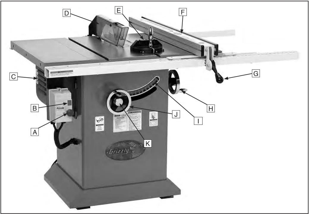
A. Emergency Stop Button
B. ON Button
C. Motor Cover
D. Blade Guard and Splitter
E. Miter Gauge
F. Rip Fence
G. Rip Fence Lock Handle
H. Blade Tilt Handwheel
I. Blade Tilt Gauge
J. Blade Height Handwheel
K. Handwheel Lock
SECTION 1: SAFETY
⚠WARNING
For Your Own Safety, Read Instruction Manual Before Operating this Machine
The purpose of safety symbols is to attract your attention to possible hazardous conditions. This manual uses a series of symbols and signal words which are intended to convey the level of importance of the safety messages. The progression of symbols is described below. Remember that safety messages by themselves do not eliminate danger and are not a substitute for proper accident prevention measures.
⚠DANGER Indicates an imminently hazardous situation which, if not avoided, WILL result in death or serious injury.
⚠WARNING Indicates a potentially hazardous situation which, if not avoided, COULD result in death or serious injury.
⚠CAUTION Indicates a potentially hazardous situation which, if not avoided, MAY result in minor or moderate injury. It may also be used to alert against unsafe practices.
NOTICE This symbol is used to alert the user to useful information about proper operation of the machine.
⚠WARNING
Safety Instructions for Machinery
- READ THROUGH THE ENTIRE MANUAL BEFORE STARTING MACHINERY. Machinery presents serious injury hazards to untrained users.
- ALWAYS USE ANSI APPROVED SAFETY GLASSES WHEN OPERATING MACHINERY. Everyday eyeglasses only have impact resistant lenses, they are NOT safety glasses.
- ALWAYS WEAR AN ANSI APPROVED RESPIRATOR WHEN OPERATING MACHINERY THAT PRODUCES DUST. Wood dust is a carcinogen and can cause cancer and severe respiratory illnesses.
- ALWAYS USE HEARING PROTECTION WHEN OPERATING MACHINERY. Machinery noise can cause permanent hearing damage.
- WEAR PROPER APPAREL. DO NOT wear loose clothing, gloves, neckties, rings, or jewelry which may get caught in moving parts. Wear protective hair covering to contain long hair and wear non-slip footwear.
- NEVER OPERATE MACHINERY WHEN TIRED, OR UNDER THE INFLUENCE OF DRUGS OR ALCOHOL. Be mentally alert at all times when running machinery.
-6- G0478 10" Hybrid Table Saw

⚠WARNING
Safety Instructions for Machinery
7. ONLY ALLOW TRAINED AND PROPERLY SUPERVISED PERSONNEL TO OPERATE MACHINERY. Make sure operation instructions are safe and clearly understood.
8. KEEP CHILDREN AND VISITORS AWAY. Keep all children and visitors a safe distance from the work area.
9. MAKE WORKSHOP CHILD PROOF. Use padlocks, master switches, and remove start switch keys.
10. NEVER LEAVE WHEN MACHINE IS RUNNING. Turn power OFF and allow all moving parts to come to a complete stop before leaving machine unattended.
11. DO NOT USE IN DANGEROUS ENVIRONMENTS. DO NOT use machinery in damp, wet locations, or where any flammable or noxious fumes may exist.
12. KEEP WORK AREA CLEAN AND WELL LIT. Clutter and dark shadows may cause accidents.
13. USE A GROUNDED EXTENSION CORD RATED FOR THE MACHINE AMPERAGE. Undersized cords overheat and lose power. Replace extension cords if they become damaged. DO NOT use extension cords for 220V machinery.
14. ALWAYS DISCONNECT FROM POWER SOURCE BEFORE SERVICING MACHINERY. Make sure switch is in OFF position before reconnecting.
15. MAINTAIN MACHINERY WITH CARE. Keep blades sharp and clean for best and safest performance. Follow instructions for lubricating and changing accessories.
16. MAKE SURE GUARDS ARE IN PLACE AND WORK CORRECTLY BEFORE USING MACHINERY.
17. REMOVE ADJUSTING KEYS AND WRENCHES. Make a habit of checking for keys and adjusting wrenches before turning machinery ON.
18. CHECK FOR DAMAGED PARTS BEFORE USING MACHINERY. Check for binding and alignment of parts, broken parts, part mounting, loose bolts, and any other conditions that may affect machine operation. Repair or replace damaged parts.
19. USE RECOMMENDED ACCESSORIES. Refer to the instruction manual for recommended accessories. The use of improper accessories may cause risk of injury.
20. DO NOT FORCE MACHINERY. Work at the speed for which the machine or accessory was designed.
21. SECURE WORKPIECE. Use clamps or a vise to hold the workpiece when practical. A secured workpiece protects your hands and frees both hands to operate the machine.
22. DO NOT OVERREACH. Keep proper footing and balance at all times.
23. MANY MACHINES WILL EJECT THE WORKPIECETOWARDTHEOPERATOR. Know and avoid conditions that cause the workpiece to "kickback."
24. ALWAYS LOCK MOBILE BASES (IF USED) BEFORE OPERATING MACHINERY.
25. BE AWARE THAT CERTAIN WOODS MAY CAUSE AN ALLERGIC REACTION in people and animals, especially when exposed to fine dust. Make sure you know what type of wood dust you will be exposed to and always wear an approved respirator.
WARNING
Additional Safety Instructions for Table Saws
-
SAFETY ACCESSORIES. Always use the blade guard and splitter on all "through-sawing" operations. Through-sawing operations are those when the blade cuts completely through the workpiece.
-
KICKBACK. Be familiar with kickback. Kickback happens when the workpiece is thrown towards the operator at a high rate of speed. Until you have a clear understanding of kickback and how it occurs, DO NOT operate this table saw!
-
WORKPIECE CONTROL. Make sure the workpiece is placed in a stable position on the table and is either supported by the rip fence or the crosscut table during cutting operations.
-
PUSH STICK. Always use a push stick when ripping narrow stock.
-
OPERATOR POSITION. Never stand or have any part of your body directly in-line with the cutting path of the saw blade.
-
REACHING OVER SAW BLADE. Never reach behind or over the blade with either hand while the saw is running. If kickback occurs while reaching over the blade, hands or arms could be pulled into the spinning saw blade.
-
USING THE RIP FENCE AND THE MITER GAUGE. Using the rip fence as a stop block when using the miter gauge can cause kickback. Remove the rip fence when using the miter gauge and remove the miter gauge when using the rip fence.
-
STALLED BLADE. Turn the saw OFF before attempting to "free" a stalled saw blade.
-
CUTTING OPERATIONS. Avoid awkward operations and hand positions where a sudden slip could cause your hand to move into the spinning saw blade.
-
EXPERIENCING DIFFICULTIES. If at any time you are experiencing difficulties performing the intended operation, stop using the machine! Contact Tech Support at (570) 546-9663.
-
BLADE HEIGHT. Always adjust the blade to the proper height above the workpiece.
-
DAMAGED SAW BLADES. Never use blades that have been dropped or otherwise damaged.
-
SPLITTER ALIGNMENT. Only operate the saw if the splitter is aligned with the saw blade.
WARNING
Like all machinery there is potential danger when operating this machine. Accidents are frequently caused by lack of familiarity or failure to pay attention. Use this machine with respect and caution to lessen the possibility of operator injury. If normal safety precautions are overlooked or ignored, serious personal injury may occur.
CAUTION
No list of safety guidelines can be complete. Every shop environment is different. Always consider safety first, as it applies to your individual working conditions. Use this and other machinery with caution and respect. Failure to do so could result in serious personal injury, damage to equipment, or poor work results.

WARNING
Statistics prove that most common accidents among table saw users can be linked to kickback. Kickback is typically defined as the high-speed expulsion of stock from the table saw toward its operator. In addition to the danger of the operator or others in the area being struck by the flying stock, it is often the case that the operator’s hands are pulled into the blade during the kickback.
Preventing Kickback
Below are tips to avoid the most common causes of kickback:
- Only cut workpieces with at least one smooth and straight edge. DO NOT cut warped, cupped or twisted wood.
- Never attempt freehand cuts. If the workpiece is not fed parallel with the blade, a kickback will likely occur. Always use the rip fence or crosscut fence to support the workpiece.
- Make sure the splitter is aligned with the blade. A misaligned splitter can cause the workpiece to catch or bind, resulting in an increased chance of kickback. If you think that your splitter is not aligned with the blade, check it immediately!
- Take the time to check and adjust the rip fence parallel with the blade; otherwise, the chances of kickback are extreme.
- Use the splitter during every cut. The splitter maintains the kerf in the workpiece, reducing the chance of kickback.
- Feed cuts through to completion. Anytime you stop feeding a workpiece that is in the middle of a cut, the chance of binding, resulting in kickback, is greatly increased.
Protecting Yourself From Kickback
Even if you know how to prevent kickback, it may still happen. Here are some tips to protect yourself if kickback DOES occur:
- Stand to the side of the blade during every cut. If a kickback does occur, the thrown workpiece usually travels directly in front of the blade.
- Wear safety glasses or a face shield. In the event of a kickback, your eyes and face are the most vulnerable part of your body.
- Never, for any reason, place your hand behind the blade. Should kickback occur, your hand will be pulled into the blade.
- Use a push stick to keep your hands farther away from the moving blade. If a kickback occurs, the push stick will most likely take the damage that your hand would have received.
- Use featherboards, or anti-kickback devices to prevent, or slow down kickback.

Glossary Of Terms
The following is a list of common definitions, terms and phrases used throughout this manual as they relate to this table saw and woodworking in general. Become familiar with these terms for assembling, adjusting or operating this machine. Your safety is VERY important to us at Grizzly!
Arbor: Metal shaft extending from the drive mechanism, to which saw blade is mounted.
Bevel Edge Cut: Tilting the arbor and saw blade to an angle between 0° and 45° to cut a beveled edge onto a workpiece.
Blade Guard: Metal or plastic safety device that mounts over the saw blade. Its function is to prevent the operator from coming into contact with the saw blade.
Crosscut: Cutting operation in which the cross-cut fence is used to cut across the grain, or across the shortest width of the workpiece.
Dado Blade: Blade or set of blades that are used to cut grooves and rabbets.
Dado Cut: Cutting operation that uses a dado blade to cut a flat bottomed groove into the face of the workpiece.
Featherboard: Safety device used to keep the workpiece against the rip fence and against the table surface.
Kerf: The resulting cut or gap in the workpiece after the saw blade passes through during a cutting operation.
Kickback: An event in which the workpiece is propelled back towards the operator at a high rate of speed.
Parallel: Being an equal distance apart at every point along two given lines or planes. I.e. the rip fence face is parallel to the face of the saw blade.
Non-Through Cut: A sawing operation that requires the removal of the blade guard and splitter. Dado and rabbet cuts are considered Non-Through Cuts because the blade does not protrude above the top face of the wood stock. Always remember to re-install the blade guard and splitter after performing a non-through cut.
Perpendicular: Lines or planes that intersect and form right angles. I.e. the blade is perpendicular to the table surface.
Push Stick: Safety device used to push the workpiece through a cutting operation. Used most often when rip cutting thin workpieces.
Rabbet: Cutting operation that creates an L-shaped channel along the edge of the workpiece.
Splitter: Metal plate located behind the blade. It maintains the kerf opening in the wood when performing a cutting operation.
Straightedge: A tool used to check the flatness, parallelism, or consistency of a surface.
Through Cut: A sawing operation in which the workpiece is completely sawn through.
Rip Cut: Cutting operation in which the rip fence is used to cut with the grain, or across the widest width of the workpiece.
SECTION 2: CIRCUIT REQUIREMENTS
110/220V Operation
WARNING
Serious personal injury could occur if you connect the machine to the power source before you have completed the set up process. DO NOT connect the machine to the power source until instructed to do so.
Amperage Draw
The Model G0478 features 110/220V motor that is prewired for 110V and draws the following amps under maximum load:
- Motor Draw at 110V ........ 20 Amps
- Motor Draw at 220V ........ 10 Amps
Circuit Requirements
We recommend connecting this machine to a dedicated circuit with a verified ground, using the circuit breaker size given below. Never replace a circuit breaker with one of higher amperage without consulting a qualified electrician to ensure compliance with wiring codes. If you are unsure about the wiring codes in your area or you plan to connect your machine to a shared circuit, you may create a fire hazard—consult a qualified electrician to reduce this risk.
- 110V Circuit Breaker ........ 30 Amps
- 220V Circuit Breaker ........ 15 Amps
NOTICE
The Model G0478 is prewired for 110V operation. If you plan to convert your machine to run on 220V, you must rewire motor (refer to wiring diagram on Page 47 for details) and replace 110V magnetic switch with P0478053A Magnetic Switch Assembly 220V. Voltage conversion MUST be performed by an electrician or qualified service personnel.
Plug Type
The Model G0478 does not include a plug. We recommend using the following plugs (see Figure 1 and 2 for examples):
- 110V Plug & Receptacle ........ NEMA L5-30
- 220V Plug & Receptacle ........ NEMA 6-15
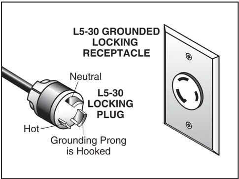
Figure 1. NEMA L5-30 plug and receptacle.
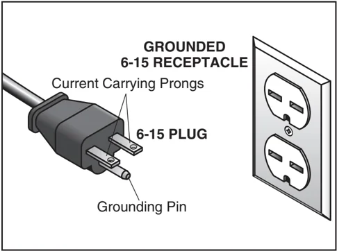
Figure 2. NEMA 6-15 plug and receptacle.
Grounding
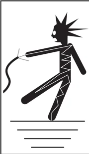
In the event of an electrical short, grounding reduces the risk of electric shock. The grounding wire in the power cord must be properly connected to the grounding prong on the plug; likewise, the outlet must be properly installed and grounded. All electrical connections must be made in accordance with local codes and ordinances.

⚠ CAUTION
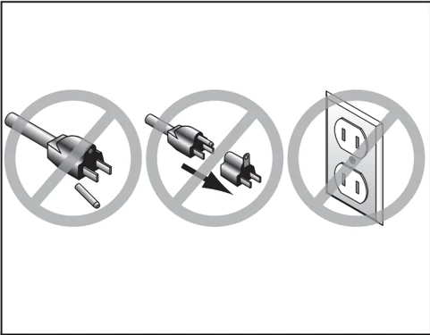
This machine must have a ground prong in the plug to help ensure that it is grounded. DO NOT remove ground prong from plug to fit into a two-pronged outlet! If the plug will not fit the outlet, have the proper outlet installed by a qualified electrician.
Extension Cords
We do not recommend the use of extension cords. Instead, arrange the placement of your equipment and the installed wiring to eliminate the need for extension cords.
If you find it absolutely necessary to use an extension cord at 110V with your machine:
-
Use at least a 12 gauge cord that does not exceed 50 feet in length!
-
The extension cord must also contain a ground wire and plug pin.
-
A qualified electrician MUST size cords over 50 feet long to prevent motor damage.
220V Operation
We do not recommend the use of extension cords. Instead, arrange the placement of your equipment and the installed wiring to eliminate the need for extension cords.
If you find it absolutely necessary to use an extension cord at 220V with your machine:
-
Use at least a 16 gauge cord that does not exceed 50 feet in length!
-
The extension cord must also contain a ground wire and plug pin.
-
A qualified electrician MUST size cords over 50 feet long to prevent motor damage.
SECTION 3: SET UP
Set Up Safety
WARNING
This machine presents serious injury hazards to untrained users. Read through this entire manual to become familiar with the controls and operations before starting the machine!
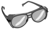
WARNING
Wear safety glasses during the entire set up process!
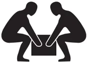
WARNING
The Model G0478 is a heavy machine (369 lbs. shipping weight). DO NOT over-exert yourself while unpacking or moving your machine—get assistance.
Items Needed For Set Up
The following items are needed to complete the set up process, but are not included with your machine:
| Description | Qty |
|---|---|
| Safety Glasses (for each person) | 1 |
| Degreaser or Solvent | Varies |
| Phillips Head Screwdriver | 1 |
| Wrench/Socket 10mm | 1 |
| Wrench/Socket 12mm | 1 |
| Wrench/Socket 17mm | 1 |
| Wrench/Socket □/□□" | 1 |
| Hex Wrench 2mm | 1 |
| Hex Wrench 5mm | 1 |
| Utility Knife or Razor Blade | 1 |
| Masking Tape | Varies |
| Straightedge | 1 |
| Dust Collection System | 1 |
| 4" Dust Hose (length as needed) | 1 |
| 4" Hose Clamps | 2 |
| Electrical Plug, 110 or 220V | 2 |
Unpacking
The Model G0478 was carefully packed when it left our warehouse. If you discover the machine is damaged after you have signed for delivery, please immediately call Customer Service at (570) 546-9663 for advice.
Save the containers and all packing materials for possible inspection by the carrier or its agent. Otherwise, filing a freight claim can be difficult.
When you are completely satisfied with the condition of your shipment, you should inventory the contents.

Inventory
After all the parts have been removed from the boxes, you should have the following items:
Table Saw Inventory (Figures 3 & 4): Qty
- A. Hybrid Table Saw (Not Shown) ........ 1
- B. Cast Iron Extension Wings ........ 2
- C. Blade Guard/Splitter Assembly ........ 1
- D. Splitter Mounting Bracket ........ 1
- E. Splitter Pivot Rod ........ 1
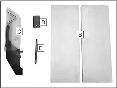
Figure 3. Table saw inventory 1.
- F. Miter Gauge ........ 1
- G. Handwheels ........ 2
- H. Handwheel Handles ........ 2
- I. Handwheel Lock Knobs ........ 2
- J. Dado Insert ........ 1
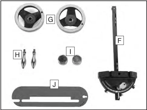
Figure 4. Table saw inventory 2.
Fence Inventory: The inventory for the Shop Fox Aluma-Classic fence and rails is located in the manual that is included in the fence box.
Tools and Hardware: (Not Shown) Qty
- —Hex Bolts 7/16"-14 x 1-1/4" ........ 6
- —Lock Washers 7/16" ........ 6
- —Hex Bolts 5/16"-18 x 1" ........ 2
- —Lock Washers 5/16" ........ 2
- —Flat Washers 5/16" ........ 4
- —Hex Nuts 1/2"-12 ........ 2
- —Flat Washers 1/2" ........ 2
- —Cap Screws 1/4"-20 x 5/8" ........ 3
- —Flat Washers 1/4" ........ 5
- —Hex Nuts 1/4"-20 ........ 2
- —Arbor Wrench ........ 1
In the event that any nonproprietary parts are missing (e.g. a nut or a washer), we would be glad to replace them, or for the sake of expediency, replacements can be obtained at your local hardware store.
-14- G0478 10" Hybrid Table Saw
Hardware Recognition Chart
USE THIS CHART TO MATCH UP HARDWARE DURING THE ASSEMBLY PROCESS.
MEASURE BOLT DIAMETER BY PLACING INSIDE CIRCLE
- #10
- 1/4"
- 5/16"
- 3/8"
- 7/16"
- 1/2"
- 4mm
- 5mm
- 6mm
- 8mm
- 10mm
- 12mm
- 16mm
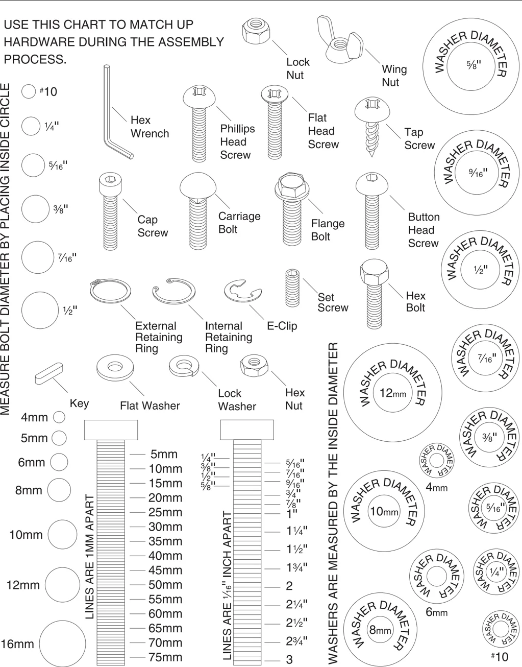
LINES ARE 1MM APART
- 5mm
- 10mm
- 15mm
- 20mm
- 25mm
- 30mm
- 35mm
- 40mm
- 45mm
- 50mm
- 55mm
- 60mm
- 65mm
- 70mm
- 75mm
LINES ARE 1/16" INCH APART
- 1/4"
- 3/8"
- 1/2"
- 5/8"
- 5/16"
- 7/16"
- 9/16"
- 3/4"
- 7/8"
- 1"
- 1 1/4"
- 1 1/2"
- 1 3/4"
- 2
- 2 1/4"
- 2 1/2"
- 2 3/4"
- 3
WASHERS ARE MEASURED BY THE INSIDE DIAMETER
Clean Up
The unpainted surfaces are coated with a waxy oil to protect them from corrosion during shipment. Remove this protective coating with a solvent cleaner or citrus-based degreaser such as Grizzly’s G7895 Degreaser. To clean thoroughly, some parts may need to be removed. For optimum performance from your machine, make sure you clean all moving parts or sliding contact surfaces that are coated. Avoid chlorine-based solvents, such as acetone or brake parts cleaner, as they may damage painted surfaces should they come in contact. Always follow the manufacturer’s instructions when using any type of cleaning product.
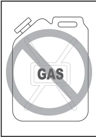
WARNING Gasoline and petroleum products have low flash points and could cause an explosion or fire if used to clean machinery. DO NOT use gasoline or petroleum products to clean the machinery.
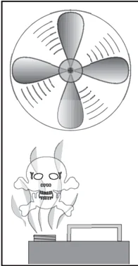
CAUTION Many of the solvents commonly used to clean machinery can be toxic when inhaled or ingested. Lack of ventilation while using these solvents could cause serious personal health risks or fire. Take precautions from this hazard by only using cleaning solvents in a well ventilated area.
Site Considerations
Floor Load
Refer to the Machine Data Sheet for the weight and footprint specifications of your machine. Some residential floors may require additional reinforcement to support both the machine and operator.
Working Clearances
Consider existing and anticipated needs, size of material to be processed through each machine, and space for auxiliary stands, work tables or other machinery when establishing a location for your new machine. See Figure 5 for the minimum working clearances.
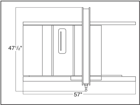
47-1/2" 57"
Figure 5. Minimum working clearances.
CAUTION Unsupervised children and visitors inside your shop could cause serious personal injury to themselves. Lock all entrances to the shop when you are away and DO NOT allow unsupervised children or visitors in your shop at any time!
Extension Wings
Components and Hardware Needed: Qty
- Extension Wings ........ 2
- Hex Bolts 7/16"-14 x 1-1/4" ........ 6
- Lock Washers 7/16" ........ 6
To install the extension wings:
- Align the extension wing holes with the holes on the cast iron table edges.
- Secure the extension wings to the cast iron table with the lock washers and hex bolts.
- Lay a straightedge across the extension wings and cast iron table surface. — If the straightedge lays flat across all three surfaces, then skip ahead to the Fence sub-section. — If either extension wing tilts down, loosen it and place a strip of masking tape along the bottom edge of the table (Figure 6).
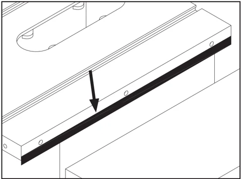
Figure 6. Masking tape location for adjusting extension table up.
— If either extension wing tilts up, loosen it and place a strip of masking tape along the top edge of the table (Figure 7).
Note: The masking tape acts as a shim, causing the table to tilt.
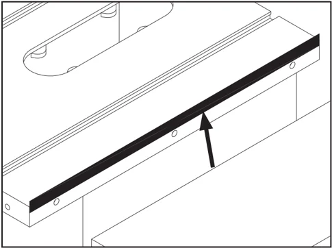
Figure 7. Masking tape location for adjusting the extension wing down.
- Once all three table surfaces are level, remove the excess masking tape with a razor blade.
- Tighten the extension wing bolts and repeat Step 3.
Fence
The Shop Fox Aluma-Classic fence and rails are installed according to the fence manual with the addition of two installation options:
—Install the fence with the end of the rails aligned with the left end of the table for a cutting capacity of 27" to the right of the blade and 11" to the left of the blade.
—Install the fence with the rails inset 3" from the left end of the table to achieve a cutting capacity of 30" to the right and 8" to the left of the blade.
NOTICE Only lift the table saw by the table top. DO NOT lift the saw by the fence rails. Lifting the saw by the fence rails can cause the table top to shift or warp, throwing the blade out of alignment.
Switch
Components and Hardware Needed:
- Hex Bolts 5/16-18 x 1" ........ 2
- Flat Washers 5/16" ........ 2
- Lock Washers 5/16" ........ 2
To install the switch:
- Bolt the switch bracket to the underside of the rail with the hex bolts and washers as shown in Figure 8.
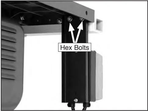
Figure 8. Installed switch.
Handwheels
Components and Hardware Needed:
- Handwheels ........ 2
- Threaded Chrome Handles 3/8"-16 x 1/2" ........ 2
- Handwheel Lock Knobs 1/2"-12 ........ 2
To install the handwheels:
-
Thread a chrome handle into each handwheel and tighten with a wrench.
-
Slide each handwheel over the threaded shafts that protrude from the side and front of the saw (Figure 9).
Note: Align the keyway on the back of each handwheel with the roll pin on the threaded shafts.
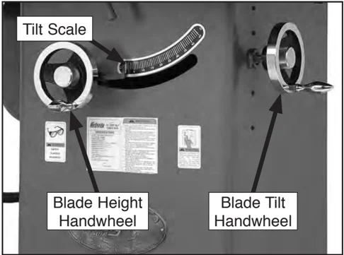
Figure 9. Installed handwheel.
-
Secure the handwheels to the threaded shaft with the handwheel lock knobs.
-
Using the blade tilt handwheel, adjust the trunnion assembly until the tilt scale reads 90°.
-18- G0478 10" Hybrid Table Saw
Blade
Components and Hardware Needed: Qty
- Blade (Not Included) ........ 1
To install the blade:
-
Use a scrap of wood pushed against the blade or a Blade Loc® (shown on Page 38) to prevent the blade from rotating, then use the arbor wrench to remove the arbor nut and arbor flange.
Note: The arbor nut has right hand threads and loosens by turning counterclockwise.
-
Slide the blade over the arbor with the teeth facing the front of the saw as shown in Figure 10.
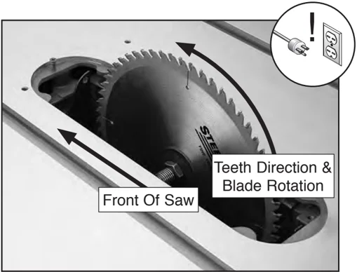
Figure 10. Correct blade direction.
- Re-install the arbor flange and the arbor nut, and tighten them against the blade.
Table Insert
Components and Hardware Needed: Qty Standard Blade Table Insert or
- Dado Blade Table Insert ........ 1
To install the table insert:
- Place the table insert into the table and tighten the screw shown in Figure 11.
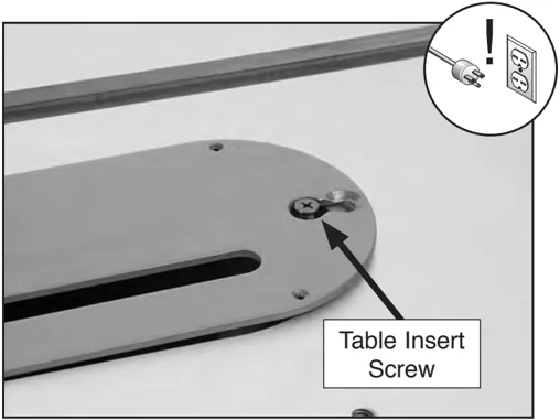
Figure 11. Table insert screw.
-
Place a straightedge across the table and the table insert.
-
Use a hex wrench to adjust the table insert flush with the table by rotating the setscrews as shown in Figure 12.
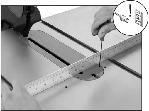
Figure 12. Adjusting the table insert.
Blade Guard
Components and Hardware Needed:
| Component/Hardware | Qty |
|---|---|
| Blade Guard/Splitter Assembly | 1 |
| Splitter Mounting Bracket | 1 |
| Splitter Pivot Shaft | 1 |
| Hex Nut 1/2"-12 | 1 |
| Flat Washer 1/2" | 1 |
| Cap Screws 1/4"-20 x 5/8" | 3 |
| Flat Washers 1/4" | 5 |
| Hex Nuts 1/4"-20 | 2 |
To install the blade guard:
- Thread the splitter pivot shaft into the trunnion as shown in Figure 13.
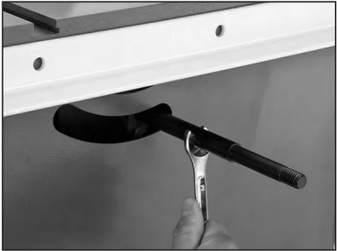
Figure 13. Installing the pivot shaft.
- Slide the splitter mounting bracket onto the shaft (Figure 14) and secure it with the 1/2"-12 hex nut and a 1/2" flat washer.
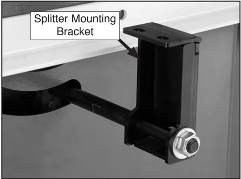
Figure 14. Blade guard mounting bracket.
- Loosely bolt the blade guard/splitter assembly onto the blade guard mounting bracket with the 1/4"-20 cap screws, washers, and hex nuts (Figure 15).
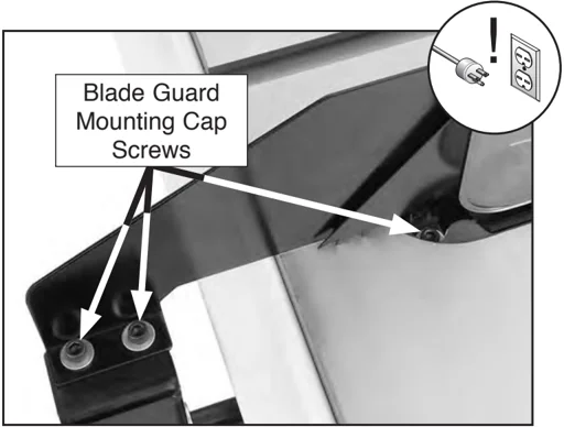
Figure 15. Blade guard mounting cap screws.
- Place a straightedge against the face of the saw blade (Figure 16) and slide the splitter over until it touches the straightedge.
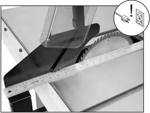
Figure 16. Checking alignment of blade guard.
G0478 □□" Hybrid Table Saw
-
Tighten the cap screws to secure the blade guard/splitter assembly.
-
Place a machinist's or a combination square against the face of the splitter as shown in Figure 17.
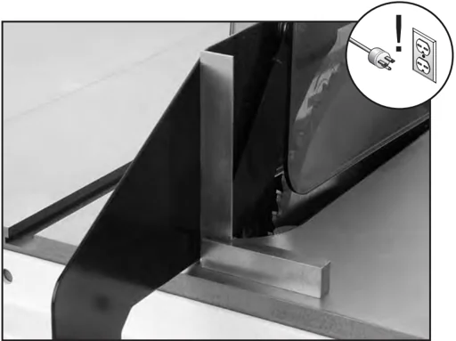
Figure 17. Blade guard perpendicular to the table.
-
Loosen the hex nut that secures the mounting bracket to the shaft and align the face of the splitter perpendicular to the table surface (Figure 17).
-
Tighten the hex nut that secures the mounting bracket to the shaft.
-
Adjust the saw blade through its complete tilt and height adjustments. The saw blade should not make contact with any part of the blade guard. If it does, re-adjust as necessary.
Recommended Adjustments
The adjustments listed below have been performed at the factory and no further setup is required to operate the machine.
However, because of the many variables involved with shipping, we recommend checking the following adjustments to ensure the best possible results from the new machine.
All of these adjustments are covered in step-by-step detail in SECTION 7: SERVICE on Page 41.
Recommended adjustment checklist:
- Blade Parallelism on Page 44.
- 45° & 90° Blade Stop on Page 46.
Test Run
 WARNING
Loose hair and clothing could get caught in machinery causing serious personal injury. Keep loose clothing rolled up and long hair tied up and away from machinery.
 WARNING
Projectiles thrown from the machine could cause serious eye injury. Wear safety glasses during the test run.
Before starting the machine:
- Read this manual and make sure you understand SECTION 1: SAFETY on Page 6.
- Review SECTION 2: CIRCUIT REQUIREMENTS on Page 11, and make any necessary changes.
- If using a 220V power source, install a NEMA 6-15 220V plug. DO NOT plug the tablesaw into the power source at this time.
- Make sure the blade guard and splitter are installed and correctly adjusted.
- Make sure all tools and foreign objects have been removed from the machine.
Starting the machine:
The Model G0478 is operated by a push button switch that is clearly labeled START/STOP.
- Plug the tablesaw into a power source.
- Put on safety glasses and hearing protection, and make sure any bystanders are wearing safety glasses, hearing protection, and are out of the way.
- Keep a finger on the STOP button at all times during the test run.
- Press the START button. —If any problems occur, immediately press the STOP button and unplug the tablesaw. Turn to Troubleshooting on Page 41 and correct the problem before operating the machine further. —If you cannot easily locate the source of an unusual noise or vibration by yourself, please contact Technical Support at (570) 546-9663.
- If the saw is behaving normally, turn it OFF and prepare to make a cut according to the instructions outlined in SECTION 4: OPERATIONS on Page 23.
SECTION 4: OPERATIONS
Operation Safety
!WARNING Damage to your eyes, lungs, and ears could result from using this machine without proper protective gear. Always wear safety glasses, a respirator, and hearing protection when operating this machine.
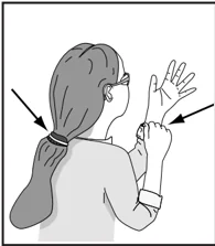
!WARNING Loose hair and clothing can get caught in machinery and cause serious personal injury. Keep loose clothing and long hair away from machinery.
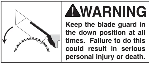
!WARNING Keep the blade guard in the down position at all times. Failure to do this could result in serious personal injury or death.
NOTICE If you have never used this type of machine or equipment before, WE STRONGLY RECOMMEND that you read books, trade magazines, or get formal training before beginning any projects. Regardless of the content in this section, Grizzly Industrial will not be held liable for accidents caused by lack of training.
Blade Selection
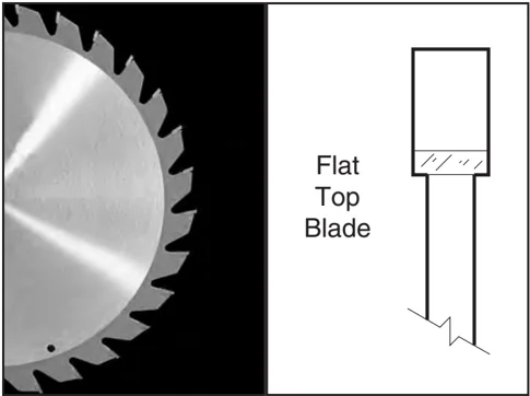
Rip blade features:
- Best for cutting with the grain of the workpiece.
- 20-40 teeth.
- Flat-top ground tooth profile.
- Large gullets for large chip removal.
Flat Top Blade
Figure 18. Rip blade.
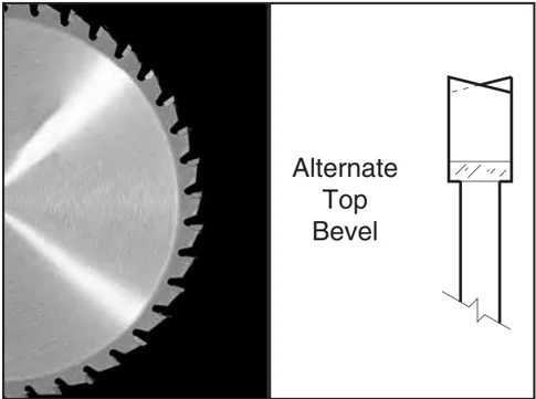
Crosscut blade features:
- Best for cutting across the grain of the workpiece.
- 60-80 teeth.
- Alternate top bevel tooth profile.
- Small hook angle and a shallow gullet.
Alternate Top Bevel
Figure 19. Crosscutting blade.

Combination blade features:
- Adequate for cutting both with and across the grain.
- 40-50 teeth.
- Alternate top bevel and flat, or alternate top bevel and raker tooth profile.
- Teeth are arranged in groups of five.
- Gullets are small and shallow within the groups of five teeth, similar to a cross-cut blade; then large and deep between each group of five, like a ripping blade.
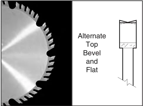
Alternate Top Bevel and Flat
Figure 20. Combination blade.
Laminate blade features:
- Best for cutting plywood or veneer.
- 40-80 teeth.
- Triple chip tooth profile.
- Very shallow gullet.
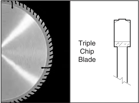
Triple Chip Blade
Figure 21. Laminate blade.
Dado Blades:
There are two types of dado blades: stacked and wobble.
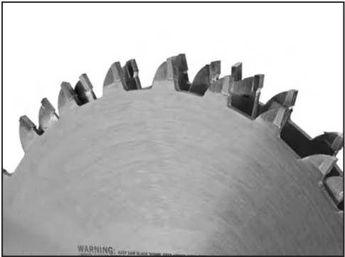
- Stacked Dado Blade: These dedicated dado cutting blade sets consist of up to 8 individual blades. Multiple cutters are "stacked" between two outside blades. The width of the dado is determined by the combination of cutters that are "stacked" together. The dado is cut in a single pass leaving a smooth and square channel in the face of the workpiece. Stacked dado blades are the most expensive option, but are worth considering if your projects require a lot of visible dado cuts. A stacked dado blade is shown in Figure 22.
WARNING
Figure 22. Stacked dado blade.
- Wobble Dado Blade: Also a dedicated dado blade, a wobble blade usually consists of a single blade that is tilted on the arbor shaft while it is spinning. The channel is cut in the face of the workpiece as the blade passes through its pre-adjusted width of travel. Wobble blades are an inexpensive option when visibly pleasing channels are not a concern.
Note: This section on blade selection is by no means comprehensive. Always follow the saw blade manufacturer's recommendations to ensure safe and efficient operation of your table saw.
Non-Through and Through Cuts
Non-Through Cuts
A non-through cut is a sawing operation where the blade does not protrude above the top face of the wood stock. Non-through cuts require the removal of the blade guard and splitter. Dado cuts, rabbet cuts, and resawing are the only non-through cuts that can be performed with this table saw.
Through Cuts
A through cut is a sawing operation in which the workpiece is completely sawn through. Ripping, crosscutting, miter cuts, and angled cuts are all through cutting operations.
Both through and non-through cuts have a risk of kickback. Kickback is an event in which the workpiece is propelled back towards the operator at a high rate of speed. Non-through cuts have a higher risk of injury from kickback because the splitter and blade guard must be removed. Always remember to re-install the blade guard and splitter after performing a non-through cut.
Read, understand, and follow the instructions and safety precautions for each type of cut to reduce the risk of injury.
Safety precautions and instructions for each type of cut are located on the following pages:
Ripping: On this page.
Crosscutting: Page 26
Miter Cuts: Page 27
Blade Tilt/Bevel Cuts: Page 27
Dado Cutting: Page 28
Rabbet Cutting: Page 30
Resawing: Page 32
Ripping
Ripping means cutting with the grain of the workpiece. In other materials such as MDF or plywood, ripping simply means cutting lengthwise.
WARNING Serious injury can be caused by kickback. Kickback is a high-speed expulsion of stock from the tablesaw toward an operator. The operator or bystanders may be struck by flying stock, or the operator’s hands can be pulled into the blade during the kickback.
To make a rip cut:
- Review Preventing Kickback on Page 9 and take the necessary precautions to prevent kickback.
- Joint one long edge of the workpiece on a jointer.
- UNPLUG THE TABLE SAW!
- Set the fence to the desired width of cut on the scale.
- Adjust the blade height so the highest saw tooth protrudes approximately 1/4" above the workpiece.
- Set up safety devices such as featherboards or other anti-kickback devices.
- Rotate the blade to make sure it does not come into contact with any of the safety devices.
Continued on next page ➡
-
Plug the saw into the power source, turn it ON, and allow it to reach full speed.
-
The jointed edge of the workpiece must slide against the fence during the cutting operation.
-
Using a push stick, feed the workpiece through the saw blade, as shown in Figure 23, until the workpiece is completely past the saw blade.
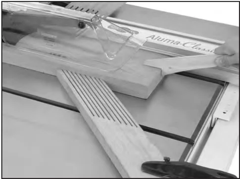
Figure 23. Ripping operation.
!WARNING Turn OFF the saw and allow the blade to come to a complete stop before removing the cut-off piece. Failure to follow this warning could result in serious personal injury.
Crosscutting
Crosscutting is cutting across the grain of the workpiece. In MDF or particleboard, crosscutting is cutting across the width of the workpiece.
To make a crosscut using the miter gauge:
-
UNPLUG THE TABLE SAW!
-
Remove the rip fence and position the miter gauge, adjusted to 90°, in a miter slot.
-
Adjust the blade height so the teeth protrude approximately 1/4" above the workpiece.
-
Slide the miter gauge near the blade and adjust the workpiece so the blade will cut on the waste side of the line.
-
Plug in the tablesaw, turn it ON, and allow it to reach full speed.
-
Hold the workpiece firmly against the face of the miter gauge and ease it into the blade as shown in Figure 24.
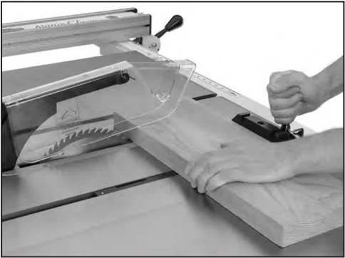
Figure 24. Crosscutting operation.
!WARNING Turn OFF the saw and allow the blade to come to a complete stop before removing the cut-off piece. Failure to follow this warning could result in serious personal injury
-26- G0478 10" Hybrid Table Saw
Miter Cuts
A miter is an angled crosscut. Miters are usually cut in the same manner as crosscuts, using the miter gauge and a predetermined mark on the workpiece.
To perform a miter cut:
- UNPLUG THE TABLE SAW!
- Determine the angle of your cut. If the angle needs to be super accurate, use a protractor to set the miter gauge to the blade.
- Place the face of the miter gauge against the edge of the workpiece and the bar across the face of the workpiece. Use the bar as a guide to mark your cut as shown in Figure 25.
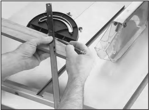
Figure 25. Marking miter line.
- Place the miter gauge back into the slot and hold the workpiece firm against the miter gauge body. Slide the miter gauge near the blade and adjust the workpiece so the blade will cut on the waste side of the line.
- Proceed to make the cut in the same manner as described in the Crosscutting instructions.
Blade Tilt/Bevel Cuts
When the positive stops are properly adjusted, the blade tilt handwheel allows the operator to tilt the blade to the left, anywhere between 0° and 45°. This is used most often when cutting bevels, compound miters or chamfers. Figure 26 shows an example of the blade when tilted to 45°.
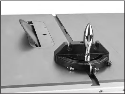
Figure 26. Blade tilted to 45° (guard removed for clarity).
Dado Cutting
Commonly used in furniture joinery, a dado is a straight channel cut in the face of the workpiece. Dadoes can be cut using either a dedicated dado blade or a standard saw blade.
The table saw motor is pushed to its limits when making a dado cut. If the motor starts to bog down, slow down your feed rate.
!WARNING
Dado operations require proper procedures to avoid serious injury. Extra care must be taken to prevent kickback when using dado blades. Any movement of the workpiece away from the fence will cause kickback. Be certain that stock is flat and straight. Failure to follow these warnings could result in serious personal injury.
!WARNING
DO NOT make a through-cut with a dado blade. Dado blades are not designed for through cuts. Failure to follow this warning could result in serious personal injury.
To use a stacked or wobble dado blade:
- UNPLUG THE TABLE SAW!
- Remove the table insert, the blade guard, and the saw blade.
- Attach and adjust the dado blade system according to the dado blade manufacturer's instructions, then install the dado insert.
- Raise the dado blade up to the desired depth of cut (depth of dado channel desired). When cutting deep dadoes, take more than one pass to reduce the risk of kickback.
!WARNING
The danger of kickback increases relative to the depth and width of a cut. Reduce the risk of kickback by making multiple passes to achieve the desired depth of cut. Failure to follow these warnings could result in serious personal injury.
- Adjust the distance between the fence and the inside edge of the blade as shown in Figure 27 to dado the length of a workpiece.
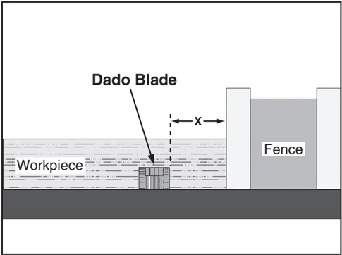
Figure 27. Stacked or wobble dado cut.
- If dadoing across the workpiece, use the miter gauge and carefully line up the desired cut with the dado blade. DO NOT use the fence in combination with the miter gauge.
- Reconnect the saw to the power source.
-
Turn the saw ON and keep one finger ready to push the STOP button. The blade should run smooth with no vibrations.
-
When the blade has reached full speed, perform a test cut with a scrap piece of wood.
-
If the cut is satisfactory, repeat the cut with the actual workpiece.
To use a standard saw blade to cut dadoes:
Note: Reduce motor overloading and blade wear by using a ripping blade. Ripping blades have between 8 and 30 teeth to clear the sawdust quickly.
-
UNPLUG THE TABLE SAW!
-
Mark the width of the dado cut on the workpiece. Include marks on the edge of the workpiece so the cut path can be aligned when the workpiece is lying on the table.
-
Raise the dado blade up to the desired depth of cut (depth of dado channel desired). When cutting deep dadoes, take more than one pass to reduce the risk of kickback.
WARNING
The danger of kickback increases relative to the depth and width of a cut. Reduce the risk of kickback by making multiple passes to achieve the desired depth of cut. Failure to follow these warnings could result in serious personal injury.
-
If dadoing across the workpiece, use the miter gauge to support the workpiece, and align the blade to cut one of the dado sides. DO NOT use the fence in combination with the miter gauge.
-
If dadoing the length of a workpiece, align the blade to cut one of the dado sides as shown in Figure 28.
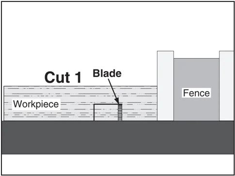
Figure 28. Single-blade dado first cut.
-
Reconnect the saw to the power source and turn the saw ON. Allow the blade to reach full speed.
-
Perform the cutting operation.
-
Re-adjust the fence so the blade is aligned with the other edge of the intended dado channel (Figure 29).
Note: Be sure to keep the cuts within your marks; otherwise, the dado will be too big.
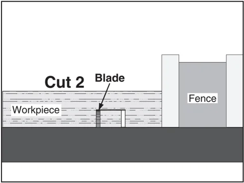
Figure 29. Single-blade dado second cut.
- Continue making cuts toward the center of the dado until the dado is complete.

Rabbet Cutting
CAUTION You may experience kickback during this procedure. Stand to the side of the blade and wear safety glasses or a face shield to prevent injury when cutting rabbets.
Commonly used in furniture joinery, a rabbet is an L-shaped groove cut in the edge of the workpiece. Rabbets can be cut with either a dado blade or a standard saw blade.
To attach a sacrificial fence:
Rabbet cutting on the edge of the workpiece requires a sacrificial fence attachment (Figure 30). Make the sacrificial fence the same length as the fence and 3/4" thick. Once the sacrificial fence has been cut, attach it to the fence with screws or clamps, making sure they are all secure and tight.
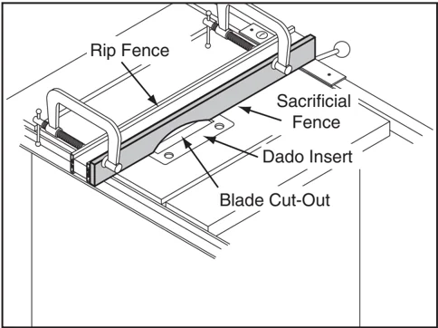
Figure 30. Sacrificial fence.
CAUTION Always use push sticks, featherboards, push paddles and other safety accessories whenever possible to increase safety and control during operations which require that the blade guard and splitter must be removed from the saw. ALWAYS replace the blade guard after dadoing is complete.
To cut rabbets with the dado blade:
-
UNPLUG THE TABLE SAW!
-
Adjust the dado blade to the height needed for the rabbeting operation. When cutting deep rabbets, take more than one pass to reduce the risk of kickback.
WARNING The danger of kickback increases relative to the depth and width of a cut. Reduce the risk of kickback by making multiple passes to achieve the desired depth of cut. Failure to follow these warnings could result in serious personal injury.
- Adjust the fence and align the workpiece to perform the cutting operation as shown in Figure 31.
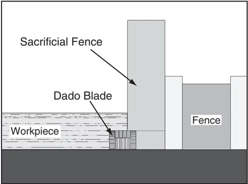
Figure 31. Rabbet cutting.
-
Reconnect the saw to the power source and turn the saw ON.
-
When the blade has reached full speed, perform a test cut with a scrap piece of wood.
-
If the cut is satisfactory, repeat the cut with the final workpiece.
To cut rabbets with the standard blade:
Note: Cutting rabbets with a standard saw blade DOES NOT require the use of a sacrificial fence.
Note: Reduce motor overloading and blade wear by using a ripping blade. Ripping blades have between 8 and 30 teeth to clear the sawdust quickly.
-
UNPLUG THE TABLE SAW!
-
Clearly mark the width of the rabbet cut on the workpiece.
Note: Include marks on the edge of the workpiece to clearly identify the intended cut while it is laying flat on the saw table.
-
Raise the blade up to the desired depth of cut (depth of rabbet channel desired). When cutting deep rabbets, take more than one pass to reduce the risk of kickback.
WARNING
The danger of kickback increases relative to the depth of a cut. Reduce the risk of kickback by making multiple passes to achieve the desired depth of cut. Failure to follow these warnings could result in serious personal injury.
- Adjust the fence so the blade is aligned with the inside of your rabbet channel as shown in Figure 32.
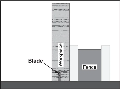
Figure 32. Rabbet cutting with a standard blade.
- Reconnect the saw to the power source and turn the saw ON.
- When the blade has reached full speed, perform a test cut with a scrap piece of wood.
- If the cut is satisfactory, repeat the cut with the final workpiece.
- Stand the workpiece on edge as shown in Figure 33.
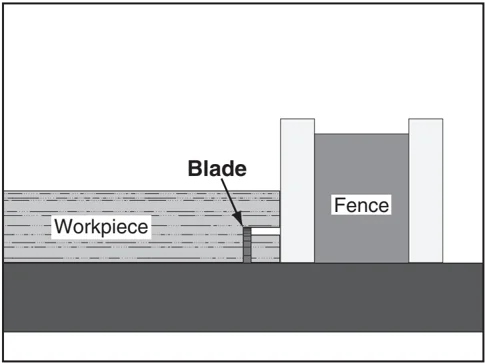
Figure 33. Second cut to create a rabbet.
- Adjust the saw blade height to intersect with the first cut.
- Perform the second cut to complete the rabbet.

Resawing
WARNING Resawing on a table saw increases the chances of kickback. Serious injury can be caused by kickback. Kickback is a high-speed expulsion of stock from the tablesaw toward an operator. The operator or bystanders may be struck by flying stock, or the operator's hands can be pulled into the blade during the kickback.
WARNING Resawing operations require proper procedures to avoid serious injury. Extra care must be taken to prevent kickback when resawing. Any tilting or movement of the workpiece away from the fence will cause kickback. Be certain that stock is flat and straight. Failure to follow these warnings could result in serious personal injury.
Resawing is the process of cutting a thick piece of stock into one or more thinner pieces. Bandsaws are ideal for resawing and the process is fairly easy and safe. A table saw is not intended for resawing and the process is difficult and extremely dangerous. Resawing on the table saw often binds the blade, causing kickback. The risk of kickback increases relative to the depth of a cut. Kickback is extra dangerous when resawing on a table saw because the anti-kickback devices and blade guard must be removed, leaving no protection between your hands and the saw blade. Kickback can pull the operator's hands into the blade, or the operator or bystanders may be hit by flying stock. DO NOT resaw on a table saw without using a resaw barrier. DO NOT resaw on a table saw without wearing a full face shield.
The following instructions describe how to build a resaw barrier, add an auxiliary fence to your standard fence, and safely perform resawing operations.
Note: This table saw can only resaw wood that is less than 6" tall.
Resaw Barrier
The resaw barrier shown in Figure 34 holds the workpiece vertical, keeps the workpiece aligned with the fence, and keeps your hands away from the blade.
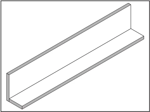
Figure 34. Resawing barrier.
Components Needed for the Resaw Barrier:
- Hardwood or Plywood 3/4" x 5-1/2" x 27" ........ 1
- Hardwood or Plywood 3/4" x 3" x 27" ........ 1
- Wood Screws 2" ........ 8
- Wood Glue ........ As Needed
Tools Needed for the Resaw Barrier:
- Table Saw ........ 1
- Jointer and Planer ........ Recommended
- Clamps ........ 2 Minimum
- Drill and Drill Bits ........ 1
To build the resaw barrier:
- Cut two boards to 3/4" x 5-1/2" x 27" and 3/4" x 3" x 27". If you are using hardwood, cut the boards oversize, then joint and plane the boards to the correct size to make sure the boards are square and flat.
Note: Only use furniture grade plywood or kiln dried hardwood to prevent warping.
- Pre-drill and countersink 8 holes approximately 3/8" from the bottom of the 5-1/2" tall board.
-32- G0478 10" Hybrid Table Saw

- Glue the end of the 3" board, then clamp the boards at a 90° angle with the larger board in the vertical position as shown in Figure 35.
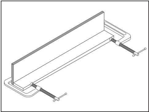
Figure 35. Clamping the resawing barrier.
- Secure the joint with the wood screws.
Auxiliary Fence
The auxiliary fence is necessary if you are resawing wood that is more than 3" tall. It should be no less than 1/2" shorter than the board to be resawn.
Components Needed for the Auxiliary Fence:
- Hardwood or Plywood 3/4" x ?" x 27" ........ 1
- Flat Head Screws 1/4-20" x 1" ........ 8
- Hex Nuts 1/4-20" ........ 8
Tools Needed for the Resaw Barrier:
- Table Saw ........ 1
- Jointer and Planer ........ Recommended
- Clamps ........ 2 Minimum
- Drill and Drill Bits ........ 1
To build the auxiliary fence:
- Cut a 3/4" thick board 27" long, and cut a height no less than 1/2" shorter than the board to be resawn. If you are using hardwood, cut the board oversize, then joint and plane the board to the correct size to make sure the board is square and flat.
Note: Only use furniture grade plywood or kiln dried hardwood to prevent warping.
-
Pre-drill and countersink 8 holes 1-1/4" from the bottom of the board.
-
Pull an end cap off of the standard fence, then slide the hex nuts into the T-slot and replace the end cap.
-
Thread the flat head screws through the auxiliary fence and into the hex nuts in the standard fence, and tighten securely as shown in Figure 36.
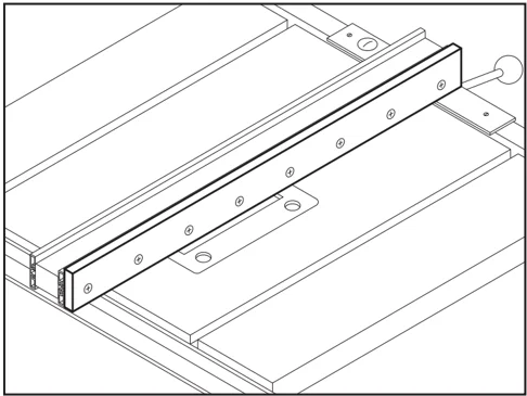
Figure 36. Auxiliary fence.
Resawing Operations
The table saw motor is pushed to its limits when resawing. If the motor starts to bog down, slow down your feed rate. Motor overloading and blade wear can be reduced by using a ripping blade. Ripping blades have between 8 and 30 teeth to clear the sawdust quickly.
Components Needed for Resawing:
- Zero Clearance Insert ........ 1
- Ripping Blade 10" ........ 1
- Clamps ........ 2
- Shop Made Auxiliary Fence ........ 1
- Shop Made Resaw Barrier ........ 1
!WARNING You may experience kickback during this procedure. Stand to the side of the blade and wear a full face shield to prevent injury when resawing.

To perform resawing operations:
-
UNPLUG THE TABLE SAW!
-
Remove the standard table insert and the blade guard/splitter. Install a ripping blade and a zero clearance insert. Then lower the blade below the table surface.
-
Attach the auxiliary fence to the standard fence and set it to the desired width.
Note: Account for blade kerf, the rough cut made by the blade, and the inaccuracy of the fence scale when the auxiliary fence is installed when figuring out the correct width.
-
Place the workpiece against the fence and slide the resaw barrier against the workpiece. Now clamp the resaw barrier to the top of the table saw (see Figure 37).
-
Slide the workpiece over the blade to make sure it moves smoothly.
-
Raise the blade approximately an inch, or close to half the height of the workpiece (Figure 37), whichever is less.
WARNING The danger of kickback increases relative to the depth of a cut. Reduce the risk of kickback by making multiple passes to achieve the desired depth of cut. Failure to follow these warnings could result in serious personal injury.
CAUTION Always use push sticks or push paddles to increase safety and control during operations which require that the blade guard and splitter must be removed from the saw. ALWAYS replace the blade guard after resawing is complete.
-
Plug in the table saw, turn it ON, and use a push stick to feed the workpiece through the blade using a slow, steady feedrate.
-
Flip the workpiece end for end, keeping the same side against the fence, and run the workpiece through the blade.
-
Repeat Steps 6–8 until the blade is close to half of the height of the board to be resawn. The ideal completed resaw cut will leave an 1/8" connection when the resawing is complete as shown in Figure 37. Leaving an 1/8" connection will reduce the risk of kickback.
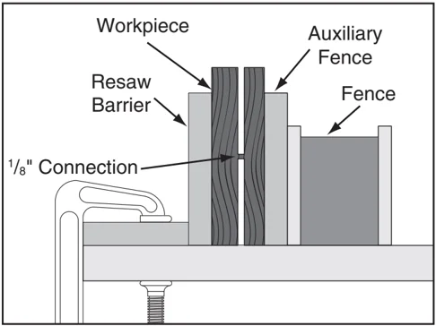
Figure 37. Ideal completed resaw cut.
-
Turn OFF the table saw, then separate the parts of the workpiece and hand plane the remaining ridge.
-
When finished resawing, remove the resaw barrier and re-install the blade guard/splitter.


SECTION 5: ACCESSORIES
G7895—Citrus Degreaser This citrus based degreaser is perfect for cleaning cosmoline off of new equipment. It also works for cleaning auto parts, tools, concrete, and porcelain surfaces. Natural, safe for the environment, and contains no CFC's.

Figure 38. G7895 Citrus Degreaser.
G1955—OxiSolv® Blade & Bit Cleaner Used to clean the gummy pitch and residue from saw blades and router bits, this high quality cleaner will make blades and bits last longer while improving cutting action.

Figure 39. G1955 OxiSolv®.
G5562—SLIPIT® 1 Qt. Gel G5563—SLIPIT® 12 oz Spray Used on cast iron table surfaces and other unpainted metal surfaces to reduce sliding friction and hang-ups. This product also reduces rust and prevents resin build-up.

Figure 40. G5562 & G5563 SLIPIT.
G2871—Boeshield® T-9 12 oz Spray G2870—Boeshield® T-9 4 oz Spray This ozone friendly protective spray penetrates deep and really holds up against corrosive environments. Lubricates metals for months and is safe for use on most paints, plastics, and vinyls.

Figure 41. Boeshield® T-9 spray.
Call 1-800-523-4777 To Order
Basic Eye Protection
- T20501—Face Shield Crown Protector 4"
- T20502—Face Shield Crown Protector 7"
- T20503—Face Shield Window
- T20451—“Kirova” Clear Safety Glasses
- T20452—“Kirova” Anti-Reflective S. Glasses
- T20456—DAKURA Safety Glasses, Black/Clear
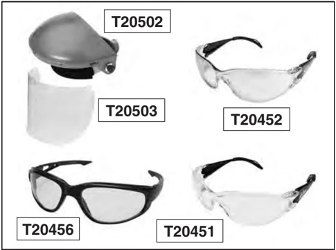
Figure 78. Assortment of basic eye protection.
Figure 42. Our most popular safety glasses.
- H2499—Small Half-Mask Respirator
- H3631—Medium Half-Mask Respirator
- H3632—Large Half-Mask Respirator
- H3635—Disposable Cartridge Filter Pair P100
Wood dust is now considered a known carcinogen and has been linked to nasal cancer and severe respiratory illnesses. If you work around dust everyday, a half-mask respirator can be a lifesaver. Also compatible with safety glasses!
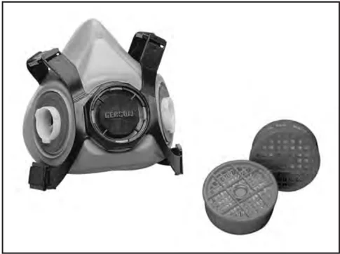
Figure 43. Half-mask respirator and disposable cartridge filters.
Carbide-Tipped Saw Blades (ATB)
- G4803—10" General Purpose, 30T
- G4804—10" General Purpose, 40T
- G4805—10" Fine Finishing/Cabinet Work, 60T
- G4806—10" Cabinet Work/Trimming, 80T
- G4807—10" Super Fine Work/Trimming, 100T
These ATB blades are manufactured to close tolerances and are fully balanced before leaving the factory. All the carbide-tipped teeth are precisely ground to give a smooth cut every time. The pattern of the teeth is alternate top bevel and the saw kerf is approx. 1/8". These blades have proven themselves in thousands of cabinet shops around the country. Manufactured for heavy-duty use.
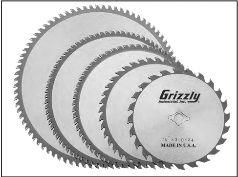
Figure 44. Carbide-tipped saw blades.
G2795—Oldham® Dado Set
This set features precision sharpened, industrial grade carbide tips for smooth, clean cutting, and a dead flat plate for straight, accurate dadoes and rabbets.
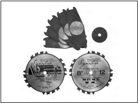
Figure 45. G2795 10" Dado Set.
Call 1-800-523-4777 To Order
H3308—SHOP FOX® Push Stick Measuring 13-1/2" overall, this push stick allows the operator to keep their hands at a safe distance away from the blade or cutter.
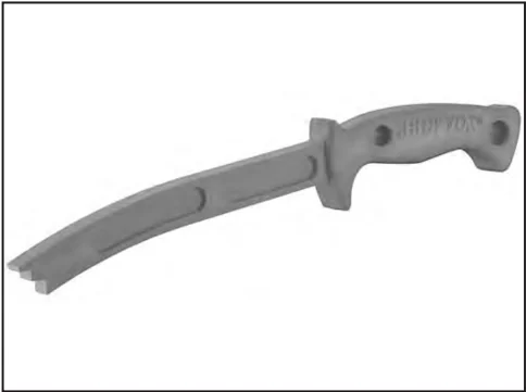
Figure 46. H3308 SHOP FOX® Push Stick.
G3445—Precision Saw Tool This high impact plastic Saw Aid™ quickly measures blade height and angle and can also serve as a solid push stick. Includes a graduated ruler guide and center finder.
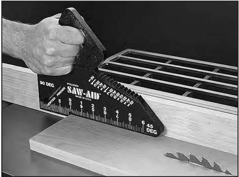
Figure 47. G3445 Precision Saw Tool.
H3309—SHOP FOX® Featherboard Designed to lock into a standard 3/8" x 3/4" miter slot, this featherboard is fully adjustable to accommodate a wide range of workpieces. Reduce the likelihood of kickback with this convenient accessory.
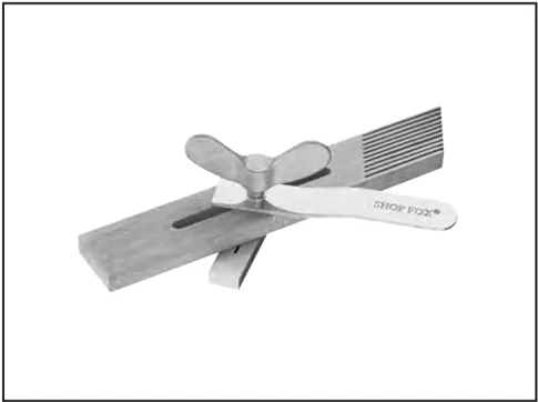
Figure 48. H3309 SHOP FOX® Featherboard.
G2370—SHOP FOX® Board Buddies These unique hold downs only turn in one direction to prevent kickback. Adjustable height, spring loaded wheels are designed to hold your workpiece tight against the table and rip fence and are made of a special composition that will not mark your work.
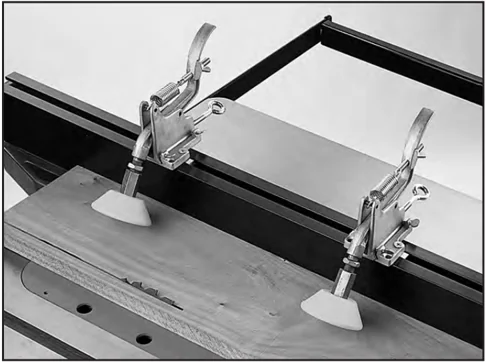
Figure 49. G2370 SHOP FOX® Board Buddies.
Call 1-800-523-4777 To Order

H7396—Zero-Clearance Table Insert Made from special phenolic material, these inserts reduce the risk of kickback and increase the efficiency of the dust collection hook-up.
 Figure 50. H7396 Zero-Clearance Table Insert.
G7581—Superbar™ G7582—Master Plate The miter slot mounted Superbar™ will align, tune and calibrate your tablesaw to within ±.001 in just minutes. Replace your tablesaw blade when calibrating the double disk ground Master Plate for a precision measurement, with no runout!
 Figure 51. Superbar™ and Master Plate.
H3771—Blade Loc® This simple tool secures the blade during blade changes, keeping your hands and your expensive blade from being damaged.
 Figure 52. H3771 Blade Loc®.
G7314—Heavy-Duty SHOP FOX® Mobile Base Make your machine mobile with this popular patented mobile base. The unique outrigger type supports increase stability and lower machine height. This heavy duty mobile base is rated for up to a 600 lb. capacity.
 Figure 53. G7314 SHOP FOX® Mobile Base.
Call 1-800-523-4777 To Order

SECTION 6: MAINTENANCE
! WARNING Always disconnect power to the machine before performing maintenance. Failure to do this may result in serious personal injury.
Schedule
For optimum performance from your machine, follow this maintenance schedule and refer to any specific instructions given in this section.
Daily
- Check guard alignment and operation.
- Inspect blades for damage.
- Check for loose mounting bolts.
- Check cords, plugs, and switch for damage.
- Any other condition that could hamper the safe operation of this machine.
- Vacuum dust buildup from inside the cabinet and off of the motor after use.
- Wipe the table clean after every use—this ensures moisture from wood dust does not remain on bare metal surfaces.
Weekly
- Wipe down the table surface and grooves with a lubricant and rust preventive such as SLIPIT®.
- Clean the pitch and resin from the saw blade with a cleaner like OxiSolv® Blade & Bit Cleaner.
Monthly
- Check the V-belt for damage or wear.
Cleaning
Cleaning the Model G0478 is relatively easy. Vacuum excess wood chips and sawdust, and wipe off the remaining dust with a dry cloth. If any resin has built up, use a resin dissolving cleaner to remove it. Treat all unpainted cast iron and steel with a non-staining lubricant after cleaning.
Occasionally it will become necessary to clean the internal parts with more than a vacuum. To do this, remove the table top and clean the internal parts with citrus cleaner or mineral spirits and a stiff wire brush or steel wool. DO NOT USE WATER—WATER WILL CAUSE CAST IRON TO RUST. Make sure the internal workings are dry before using the saw again, so that wood dust will not accumulate. If any essential lubrication is removed during cleaning, re-lubricate those areas.
Lubrication
Lubricate the areas indicated below every 6–12 months, depending on frequency of use.
- Blade angling trunnions. These should be lubricated with 6 or 7 drops of light machine oil.
- Blade height trunnion. This should also be lubricated with 6 or 7 drops of light machine oil.
- The 2 worm gears should be lubricated with an automotive wheel bearing grease.
These points can be reached through the motor cover opening or the blade opening. Check all adjustments after lubricating.
Maintenance Log
This page is for tracking frequency of lubrication and other maintenance procedures to ensure that they are performed at the scheduled intervals.
| Date | Approximate Hours Of Use | Maintenance Performed |
|---|---|---|
-40- G0478 10" Hybrid Table Saw
SECTION 7: SERVICE
This section is provided for your convenience—it is not a substitute for the Grizzly Service Department. If you need help troubleshooting, you need replacement parts, or you are unsure of how to perform the procedures in this section, then feel free to call our Technical Support at (570) 546-9663.
Troubleshooting
Motor & Electrical
| SYMPTOM | POSSIBLE CAUSE | CORRECTIVE ACTION |
|---|---|---|
| Machine does not start or a breaker trips. | 1. Plug or receptacle is at fault or wired incorrectly.2. Start capacitor is faulty.3. The thermal protection relay below the motor contactor is tripped.4. Contactor not getting energized or has burnt contacts.5. Wall fuse or circuit breaker is blown or tripped.6. Motor connection is wired incorrectly.7. Power supply is faulty, or is switched OFF.8. Motor ON button.9. Centrifugal switch is at fault.10. Cable or wiring is open or has high resistance.11. Motor is at damaged. | 1. Test power plug and receptacle for good contact and correct wiring.2. Replace start capacitor.3. If no short exists, turn the cut-out dial on the relay (see Page 48) to increase working amps, and push the reset pin, or replace weak relay.4. Replace contactor.5. Make sure circuit breaker/fuse is sized correctly for machine load (refer to Page 11), or replace weak breaker.6. Correct motor wiring (see Page 47).7. Make sure all hot lines and grounds are operational and have correct voltage.8. Replace faulty ON button.9. Adjust or repair centrifugal switch.10. Troubleshoot wires for internal or external breaks, and disconnected or corroded connections; repair or replace wiring.11. Repair or replace motor. |
| Machine stalls or is underpowered. | 1. Applying too much pressure to workpiece.2. Low power supply voltage.3. Run capacitor is faulty.4. Belt is slipping.5. Plug or receptacle is at fault.6. Motor connection is wired incorrectly.7. Pulley or sprocket is slipping on shaft.8. Motor bearings are at fault.9. Motor has overheated.10. Contactor not getting energized or has poor contacts.11. Motor is at fault.12. Centrifugal switch is at fault. | 1. Use sharp blade, and reduce the feed rate.2. Make sure all hot lines and grounds are operational and have correct voltage.3. Replace run capacitor.4. Replace belt and/or re-tension.5. Test power plug and receptacle for good contact and correct wiring.6. Correct motor wiring (see Page 47).7. Replace loose pulley and shaft.8. Rotate motor shaft for noisy or burnt bearings, replace as required.9. Let motor cool, clean motor fan cover, and reduce workload on machine.10. Replace contactor.11. Repair or replace motor.12. Repair or replace centrifugal switch. |
| SYMPTOM | POSSIBLE CAUSE | CORRECTIVE ACTION |
|---|---|---|
| Machine has vibration or noisy operation. | 1. Loose arbor nut.2. Blade is damaged.3. Blade is too thin.4. Machine is sitting on an uneven floor.5. Belt is worn or is loose.6. Pulley is loose.7. Cast iron motor mount is damaged.8. Arbor bearings are damaged.9. Motor bearings are damaged.10. Wrong workpiece material (wood). | 1. Tighten the arbor nut.2. Replace warped/ bent/ or twisted blade;.3. Use blade stabilizers.4. Relocate machine or shim feet.5. Inspect belt, replace or re-tension.6. Remove pulley; replace shaft, pulley, and setscrew as required, and re-align.7. Carefully using leverage and a small pry bar, carefully look for loose/broken mounts and replace if necessary.8. Replace arbor housing bearings.9. Replace motor bearings.10. Only process wood with correct moisture content, with no pitch, glues, or resins. |
Table Saw Operations
| SYMPTOM | POSSIBLE CAUSE | CORRECTIVE ACTION |
|---|---|---|
| Blade is not aligned with miter slot or fence. | 1. Blade is warped.2. Blade is not parallel to table top.3. Fence is not parallel to blade. | 1. Replace blade.2. Make blade parallel to table.3. Make fence parallel to blade. |
| Fence hits table top when sliding. | 1. Front rail is bolted too low on table.2. Rear rail is bolted too low on the table. | 1. Raise front rail.2. Raise rear rail. |
| Blade does not reach 90°. | 1. 90° stop bolt is out of adjustment.2. Pointer bracket is hitting before the blade reaches 90°. | 1. Adjust 90° stop bolt.2. File down the right side of the pointer bracket until the blade can reach 90°. |
| Blade hits insert at 45°. | 1. Hole in insert is inadequate.2. Table out of alignment.3. Blade position is incorrect. | 1. File or mill the hole in the insert.2. Align blade to the table.3. Adjust blade position. |
| Blade will not go beneath table surface. | 1. Table top too low. | 1. Lower the blade trunnion w/washers. |
| Board binds or burns when feeding through tablesaw. | 1. Dull blade.2. Blade is warped.3. Table top is not parallel to blade.4. Splitter out of alignment.5. Fence is not parallel to blade. | 1. Replace blade.2. Replace blade.3. Make table parallel to blade.4. Align the splitter with the blade.5. Make fence parallel to blade. |
Replacing Flat Belt
To ensure optimum power transmission from the motor to the blade, the flat belt must be in good condition. Replace the belt if it becomes cracked, frayed, or glazed.
Tools Needed Qty
- Arbor Wrench ........ 1
- Hex Wrench 6mm ........ 1
- Phillips Head Screwdriver ........ 1
To replace the flat belt:
- UNPLUG THE TABLE SAW!
- Adjust the blade all the way up and tilt it to 45°.
- Remove the table insert, arbor nut, flange, and the saw blade.
- Remove the belt cover plate shown in Figure 54. The cover plate is held in place by two tabs that fit into holes in the trunnion. Pull the ends of the cover plate out to release the tabs from the trunnion.
 Figure 54. Removing the belt cover plate.
- Lower the blade all the way down, loosen the tensioning screw (Figure 55), then rotate the motor to release the tension on the flat belt.
 Tensioning
Screw
Figure 55. Flat belt tensioning screw.
- Pull the flat belt out through the table and install the new belt, then lower the motor to apply tension and tighten the cap screw loosened in Step 6.
- Replace the belt cover plate and the blade.
Blade Parallelism
Tools Needed
| Tool | Qty |
|---|---|
| Adjustable Square | 1 |
| Feeler Gauge Set | 1 |
| Wrench 12mm | 1 |
| Shims | As Needed |
To check and adjust blade parallelism:
-
Unplug the tablesaw!
-
Raise the blade to its highest position and tilt it to 90°.
-
Using an adjustable square, measure the distance (A) between the miter slot and the front of the blade as shown in Figure 56.
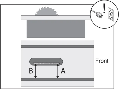
Figure 56. 90° blade parallelism measurement.
-
Rotate the blade 180° and slide the adjustable square to position B.
-
Measure the difference between the two positions with a feeler gauge. Make note of the difference between the two measurements on a piece of paper.
-
Tilt the blade to 45° and repeat Steps 3–5. —If the difference was less than 0.004" when the blade was positioned at 90° and 45°, then the blade parallelism is correct. Skip to 45° & 90° Stops on Page 46. —If the difference was greater than 0.004" when the blade was positioned at 90° or 45°, then the trunnion assembly below the table needs to be adjusted. Continue with the next step.
-
Loosen the trunnion bolts shown in Figure 57.
Note: It may be easiest to reach some of the bolts through the hole in the table.
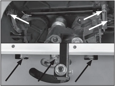
Figure 57. Trunnion bolt locations (not all the trunnion bolts are shown).
- Refer back to the measurements taken in Steps 3-6. —If the blade was not parallel in the 90° position, then proceed to the set of instructions titled To Shift The Trunnion on Page 45. —If the blade was not parallel in the 45° position, then proceed to the set of instructions titled To Shim The Trunnion on Page 45.
G0478 □□" Hybrid Table Saw
To shift the trunnion:
- Loosen the trunnion bolts (Figure 57).
- Move the trunnion assembly according to the difference measured when the blade was in the 90° position.
- Tighten down one trunnion bolt a small amount and then move on to each of the others, tightening each down the same amount.
- Continue to rotate through the bolts, tightening them a little each time until they are all secure.
- Once the miter slot is adjusted parallel to the blade, recheck all measurements and be sure the table mounting bolts are secure.
To shim the trunnion:
- Loosen the trunnion bolts (Figure 57).
- Using Figure 58, shim the trunnion assembly according to the difference measured when the blade was in the 45° position. —If the distance of A is shorter than B, shims will need to be placed between the rear trunnion bolts and the table top. —If the distance of B is shorter than A, shims will need to be placed between the front trunnion bolts and the table top
Note: Very thin shims work best. Make sure they are all the same thickness, and put an equal number under each of the two corners.
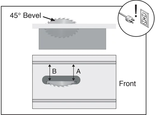
Figure 58. 45° blade parallelism measurement.
- Tighten down one trunnion bolt a small amount and then move on to each of the others, tightening each down the same amount.
- Continue to rotate through the bolts, tightening them a little each time until they are all secure.
- Once the miter slot is adjusted parallel to the blade, recheck all measurements and be sure the table mounting bolts are secure.
NOTICE If the trunnion assembly is loosened in the future, make note of the shim locations and re-assemble accordingly.
45° & 90° Stops
The Model G0478 Table Saw is equipped with positive stops at 45° and 90°. When properly adjusted, they provide quick and precise guides for blade bevel adjustment.
To set the 45° & 90° stops:
- UNPLUG THE TABLESAW!
- Raise the saw blade to its maximum height and adjust the blade to the 90° position.
- Place a 90° machinist's square between the teeth on the blade and on the table surface, as shown in Figure 59.
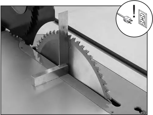
Figure 59. Checking blade angle to table.
- With the square in place, inspect for gaps between the blade and the square.
- If a gap exists at either the top or bottom of the square, turn the handwheel until the blade and square are flush.
- Loosen the 90° set screw shown in Figure 60, and then tighten it until it stops.
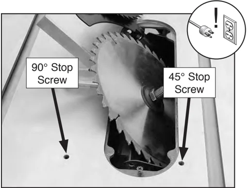
Figure 60. 90° and 45° stop screws.
- Recheck the blade with the square to ensure the screw has not been over-tightened.
- Using the side handwheel, adjust the blade bevel until you hit the 45° positive stop. Check the bevel with an adjustable square set to 45°.
- If a gap exists at either the top or bottom of the adjustable square, turn the handwheel until the blade and square are flush.
- Loosen the 90° set screw shown in Figure 60, and then tighten it until it stops.
- Recheck the bevel by adjusting the blade back to 90°, then back to 45°.
G0478 110/220V Wiring Diagram
Grizzly Industrial, Inc.
Model G0478 Wiring Diagram
110/220 Volt Single-Phase

NOTICE
The Model G0478 is prewired for 110V operation. If you plan to convert your machine to run on 220V, you must rewire motor and replace 110V magnetic switch with P0478053A Magnetic Switch Assembly 220V. Voltage conversion MUST be performed by an electrician or qualified service personnel.
Note:
the wires from the power supply, except the green ground wire, are interchangable, therefore colors are not specified.
Note:
the wires from the power supply, except the green ground wire, are interchangable, therefore colors are not specified.
DANGER
Disconnect power from machine before performing any electrical service. Failure to do this will result in a shock hazard leading to injury or death.
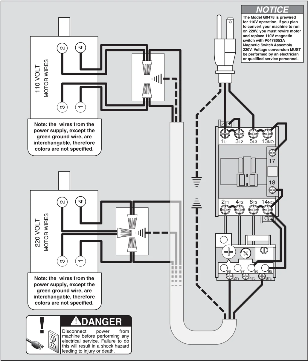
Electrical Components
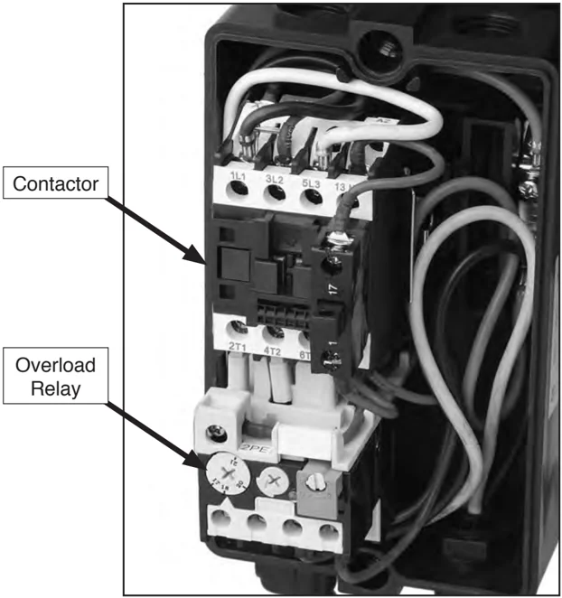
Figure 61. Magnetic switch components.
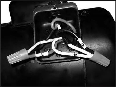
Figure 62. 110V motor wiring.
-48- G0478 10" Hybrid Table Saw
Parts Breakdown
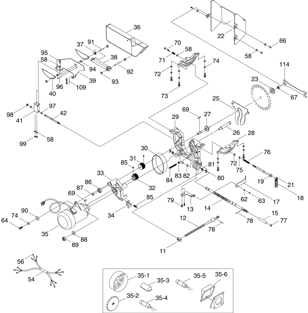
Parts Breakdown
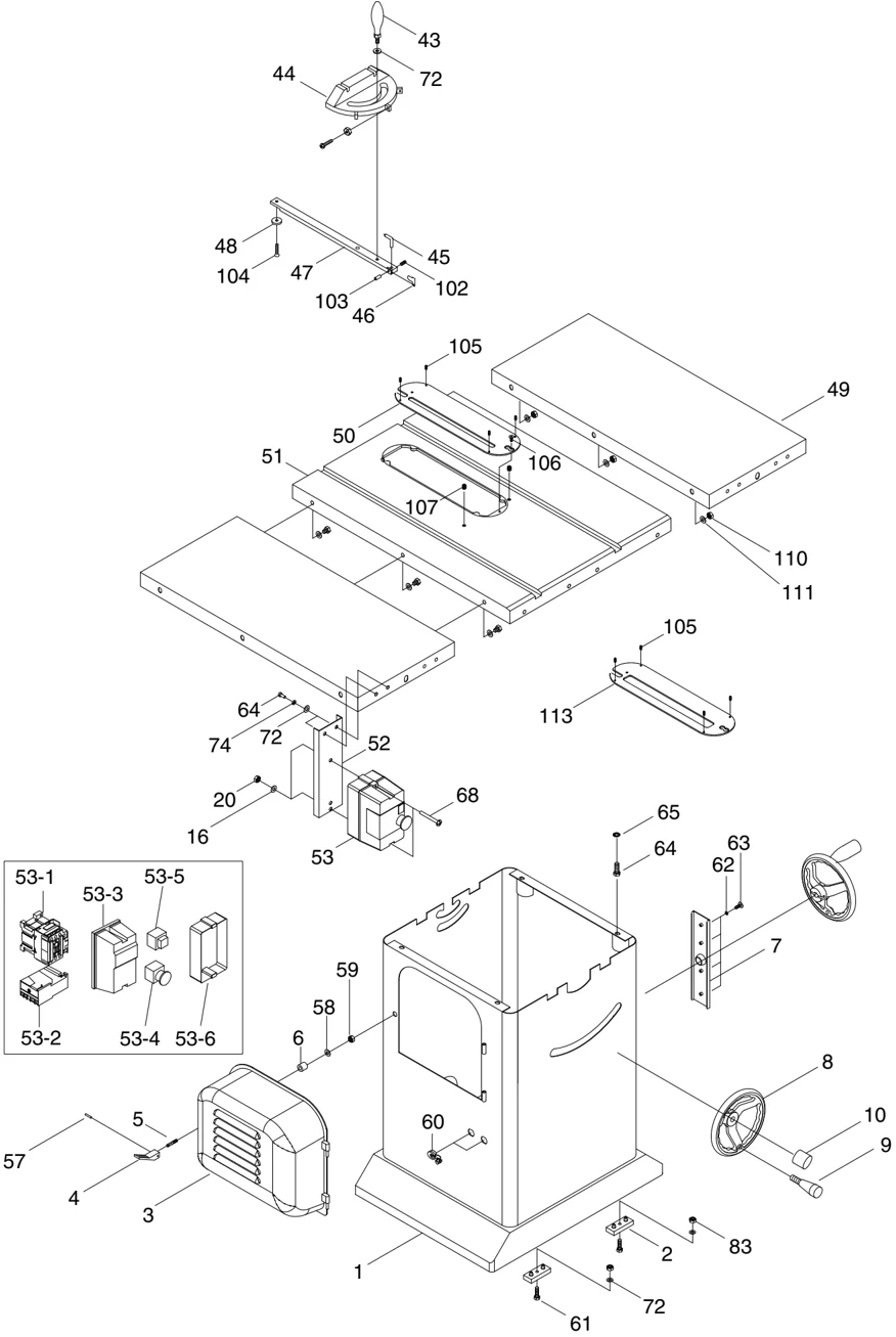
Safety Labels
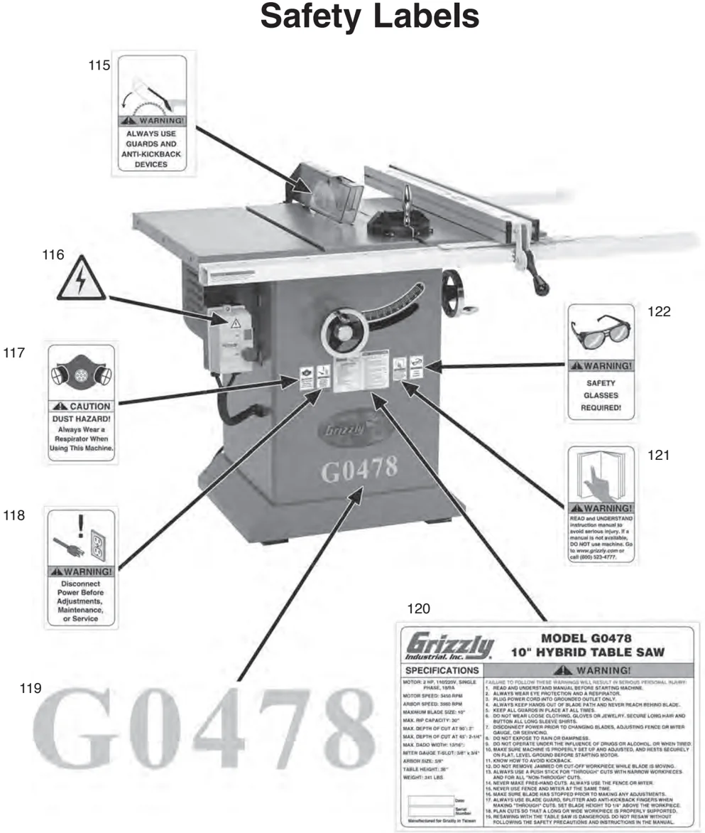
115 WARNING! ALWAYS USE GUARDS AND ANTI-KICKBACK DEVICES
116 (Icon: Lightning bolt in triangle)
117 CAUTION DUST HAZARD! Always Wear a Respirator When Using This Machine.
118 WARNING! Disconnect Power Before Adjustments, Maintenance, or Service
119 G0478
120 Grizzly Industrial, Inc. MODEL G0478 10" HYBRID TABLE SAW
SPECIFICATIONS MOTOR: 2 HP, 110/220V, SINGLE PHASE, 18/9A MOTOR SPEED: 3450 RPM ARBOR SPEED: 3860 RPM MAXIMUM BLADE SIZE: 10" MAX. RP CAPACITY: 90° MAX. DEPTH OF CUT AT 90°: 2-3/4" MAX. DEPTH OF CUT AT 45°: 2-1/4" MAX. DADO WIDTH: 13/16" MITER GAUGE T-SLOT: 5/8" X 3/4" ARBOR SIZE: 5/8" TABLE HEIGHT: 36" WEIGHT: 341 LBS.
WARNING! FAILURE TO FOLLOW THESE WARNINGS WILL RESULT IN SERIOUS PERSONAL INJURY:
- READ AND UNDERSTAND MANUAL BEFORE STARTING MACHINE.
- ALWAYS WEAR EYE PROTECTION AND A RESPIRATOR.
- PLUG POWER CORD INTO GROUNDED OUTLET ONLY.
- ALWAYS KEEP HANDS OUT OF BLADE PATH AND NEVER REACH BEHIND BLADE.
- KEEP ALL GUARDS IN PLACE AT ALL TIMES.
- DO NOT WEAR LOOSE CLOTHING, GLOVES OR JEWELRY. SECURE LONG HAIR AND BUTTON ALL LONG SLEEVE SHIRTS.
- DISCONNECT POWER PRIOR TO CHANGING BLADES, ADJUSTING FENCE OR MITER GAUGE, OR SERVICING.
- DO NOT EXPOSE TO RAIN OR DAMPNESS.
- DO NOT OPERATE UNDER THE INFLUENCE OF DRUGS OR ALCOHOL, OR WHEN TIRED.
- MAKE SURE MACHINE IS PROPERLY SET UP AND ADJUSTED, AND RESTS SECURELY ON FLAT, LEVEL GROUND BEFORE STARTING MOTOR.
- KNOW HOW TO AVOID KICKBACK.
- DO NOT REMOVE JAMMED OR CUT-OFF WORKPIECE WHILE BLADE IS MOVING.
- ALWAYS USE A PUSH STICK FOR "THROUGH" CUTS WITH NARROW WORKPIECES, AND FOR ALL "NON-THROUGH" CUTS.
- NEVER MAKE FREE-HAND CUTS. ALWAYS USE THE FENCE OR MITER.
- NEVER USE FENCE AND MITER AT THE SAME TIME.
- MAKE SURE BLADE HAS STOPPED PRIOR TO MAKING ANY ADJUSTMENTS.
- ALWAYS USE BLADE GUARD, SPLITTER AND ANTI-KICKBACK FINGERS WHEN MAKING "THROUGH" CUTS. SET BLADE HEIGHT TO 1/8" ABOVE THE WORKPIECE.
- PLAN CUTS SO THAT A LONG OR WIDE WORKPIECE IS PROPERLY SUPPORTED.
- RESAWING WITH THE TABLE SAW IS DANGEROUS. DO NOT RESAW WITHOUT FOLLOWING THE SAFETY PRECAUTIONS AND INSTRUCTIONS IN THE MANUAL.
Date Serial Number Manufactured for Grizzly in Taiwan
121 WARNING! READ and UNDERSTAND instruction manual to avoid serious injury. If a manual is not available, DO NOT use machine. Go to www.grizzly.com or call (800) 523-4777.
122 WARNING! SAFETY GLASSES REQUIRED!
WARNING
Safety labels warn about machine hazards and ways to prevent injury. The owner of this machine MUST maintain the original location and readability of the labels on the machine. If any label is removed or becomes unreadable, REPLACE that label before using the machine again. Contact Grizzly at (800) 523-4777 or www.grizzly.com to order new labels.
Parts List
| REF | PART # | DESCRIPTION |
|---|---|---|
| 1 | P0478001 | CABINET |
| 2 | P0478002 | PLASTIC FOOT |
| 3 | P0478003 | MOTOR COVER |
| 4 | P0478004 | DOOR RELEASE LEVER |
| 5 | P0478005 | THREADED ROD M6-1 |
| 6 | P0478006 | RUBBER BUSHING |
| 7 | P0478007 | BRACKET |
| 8 | P0478008 | HANDWHEEL |
| 9 | P0478009 | HANDLE 3/8 X 110MM (STEEL) |
| 10 | P0478010 | LOCK KNOB 1/2-12 |
| 11 | P0478011 | TILT LEADSCREW NUT |
| 12 | P0478012 | LONG SHAFT |
| 13 | P0478013 | POINTER BRACKET |
| 14 | P0478014 | ELEVATION LEADSCREW |
| 15 | P0478015 | SLEEVE |
| 16 | P0478016 | FLAT WASHER #10 |
| 17 | P0478017 | POINTER |
| 18 | P0478018 | LOCK HANDLE |
| 19 | P0478019 | LOCK ROD |
| 20 | P0478020 | HEX NUT 10-24 |
| 21 | P0478021 | LOCK HANDLE |
| 22 | P0478022 | DUST COLLECTING PLATE |
| 23 | P0478023 | ARBOR FLANGE |
| 25 | P0478025 | MOTOR PLATE |
| 26 | P0478026 | ARBOR BRACKET SHAFT |
| 27 | P0478027 | MAIN ARBOR |
| 28 | P0478028 | FR TRUNNION BRACKET |
| 29 | P0478029 | MAIN TRUNNION |
| 30 | P0478030 | BELT 150J X 12 |
| 31 | P0478031 | ARBOR PULLEY |
| 32 | P0478032 | MOTOR PULLEY |
| 33 | P0478033 | ARBOR BRACKET |
| 34 | P0478034 | UPPER STOP |
| REF | PART # | DESCRIPTION |
|---|---|---|
| 35 | P0478035 | MOTOR |
| 35-1 | P0478035-1 | MOTOR FAN COVER |
| 35-2 | P0478035-2 | MOTOR FAN |
| 35-4 | P0478035-4 | CAPACITOR 30M 250V |
| 35-5 | P0478035-5 | CAPACITOR 400M 125VAC |
| 35-6 | P0478035-6 | WIRING BOX |
| 36 | P0478036 | BLADE GUARD |
| 37 | P0478037 | TORSION SPRING |
| 38 | P0478038 | SUPPORT ARM |
| 39 | P0478039 | SPLITTER |
| 40 | P0478040 | ANTI-KICK PLATE |
| 41 | P0478041 | SPLITTER BRACKET |
| 42 | P0478042 | SPLITTER ROD |
| 43 | P0478043 | MITER GAUGE HANDLE |
| 44 | P0478044 | MITER GAUGE BODY |
| 45 | P0478045 | POINTER |
| 46 | P0478046 | LOCATING PLATE |
| 47 | P0478047 | MITER BAR |
| 48 | P0478048 | SPECIAL WASHER 1/4 |
| 49 | P0478049 | SOLID EXTENSION WING |
| 50 | P0478050 | TABLE INSERT |
| 51 | P0478051 | TABLE |
| 52 | P0478052 | SWITCH BRACKET |
| 53 | P0478053 | MAGNETIC SWITCH ASSEMBLY 110V |
| 53A | P0478053A | MAGNETIC SWITCH ASSY 220V 2HP |
| 53-1 | P0478053-1 | CONTACTOR 110V TAI-CYUAN |
| 53-2 | P0478053-2 | RELAY 110V TAI-CYUAN |
| 53-3 | P0478053-3 | FRONT COVER |
| 53-4 | P0478053-4 | STOP BUTTON |
| 53-5 | P0478053-5 | START BUTTON |
| 53-6 | P0478053-6 | BACK COVER |
| 54 | P0478054 | CORD SLEEVE |
G0478 □□" Hybrid Table Saw
Parts List
| REF | PART # | DESCRIPTION |
|---|---|---|
| 56 | P0478056 | POWER CORD 110V, SHORT |
| 57 | P0478057 | ROLL PIN 3 X 18 |
| 58 | P0478058 | FLAT WASHER 1/4 |
| 59 | P0478059 | LOCK NUT M6-1 |
| 60 | P0478060 | STRAIN RELIEF |
| 61 | P0478061 | PHLP HD SCR 5/16-18 X 5/8 |
| 62 | P0478062 | FLAT WASHER #8 |
| 63 | P0478063 | PHLP HD SCR 8-32 X 3/8 |
| 64 | P0478064 | HEX BOLT 5/16-18 X 5/8 |
| 65 | P0478065 | EXT TOOTH WASHER 8MM |
| 66 | P0478066 | PHLP HD SCR 1/4-20 X 1/2 |
| 67 | P0478067 | FLANGE NUT TW 5/8-12 |
| 68 | P0478068 | FLANGE SCR 10-24 X 9/16 |
| 69 | P0478069 | KEY 5 X 5 X 40 |
| 70 | P0478070 | SPECIAL BOLT 1/4-20 X 40 |
| 71 | P0478071 | COMPRESSION SPRING |
| 72 | P0478072 | FLAT WASHER 5/16 |
| 73 | P0478073 | HEX BOLT 5/16-18 X 1 |
| 74 | P0478074 | LOCK WASHER 5/16 |
| 75 | P0478075 | EXT RETAINING RING 10MM |
| 76 | P0478076 | COMPRESSION SPRING |
| 77 | P0478077 | FLAT WASHER 14MM |
| 78 | P0478078 | ROLL PIN 5 X 40 |
| 79 | P0478079 | PHLP HD SCR 1/4-20 X 1/2 |
| 80 | P0478080 | EXT RETAINING RING 16MM |
| 81 | P0478081 | WAVY WASHER 16MM |
| 82 | P0478082 | EXT RETAINING RING 16MM |
| 83 | P0478083 | HEX NUT 5/16-18 |
| 84 | P0478084 | HEX BOLT 5/16-18 X 3 |
| 85 | P0478085 | SET SCREW 1/4-20 X 1/4 |
| 86 | P0478086 | BALL BEARING 6202-2RS 5/8 |
| 87 | P0478087 | EXT RETAINING RING 15MM |
| REF | PART # | DESCRIPTION |
|---|---|---|
| 88 | P0478088 | FLAT WASHER 5/8 |
| 89 | P0478089 | NYLON NUT 5/8-11 |
| 90 | P0478090 | FLAT WASHER 5/16 |
| 91 | P0478091 | SHORT PIN 6 X 33 |
| 92 | P0478092 | LONG PIN 6 X 47 |
| 93 | P0478093 | RETAINER |
| 94 | P0478094 | SPACER |
| 95 | P0478095 | CAP SCREW 5/16-18 X 1 |
| 96 | P0478096 | ROLL PIN 6 X 20 |
| 97 | P0478097 | FLAT WASHER 1/2 |
| 98 | P0478098 | HEX NUT 1/2-12 |
| 99 | P0478099 | HEX NUT 5/16-18 |
| 102 | P0478102 | SET SCREW 1/4-20 X 1/4 |
| 103 | P0478103 | ROLL PIN 3 X 6 |
| 104 | P0478104 | FLAT HD SCR 1/4-20 X 3/8 |
| 105 | P0478105 | SET SCREW 10-24 X 3/16 |
| 106 | P0478106 | FLAT HD SCR 10-24 X 3/4 |
| 107 | P0478107 | SET SCREW 5/16-18 X 5/8 |
| 109 | P0478109 | CAP SCREW 5/16-18 X 1 |
| 110 | P0478110 | HEX BOLT 7/16-14 X 1-1/4 |
| 111 | P0478111 | LOCK WASHER 7/16 |
| 113 | P0478113 | DADO INSERT |
| 114 | P0478114 | ARBOR WRENCH 12 X 23 |
| 115 | P0478115 | BLADE GUARD LABEL |
| 116 | P0478116 | ELECTRICITY LABEL |
| 117 | P0478117 | RESPIRATOR LABEL |
| 118 | P0478118 | UNPLUG TABLE SAW LABEL |
| 119 | P0478119 | MODEL NUMBER LABEL |
| 120 | P0478120 | MACHINE ID LABEL |
| 121 | P0478121 | READ MANUAL 2"W X 3 5/16" |
| 122 | P0478122 | SAFETY GLASSES 2" X 3 5/16" |
WARRANTY AND RETURNS
Grizzly Industrial, Inc. warrants every product it sells for a period of 1 year to the original purchaser from the date of purchase. This warranty does not apply to defects due directly or indirectly to misuse, abuse, negligence, accidents, repairs or alterations or lack of maintenance. This is Grizzly's sole written warranty and any and all warranties that may be implied by law, including any merchantability or fitness, for any particular purpose, are hereby limited to the duration of this written warranty. We do not warrant or represent that the merchandise complies with the provisions of any law or acts unless the manufacturer so warrants. In no event shall Grizzly's liability under this warranty exceed the purchase price paid for the product and any legal actions brought against Grizzly shall be tried in the State of Washington, County of Whatcom.
We shall in no event be liable for death, injuries to persons or property or for incidental, contingent, special, or consequential damages arising from the use of our products.
To take advantage of this warranty, contact us by mail or phone and give us all the details. We will then issue you a "Return Number," which must be clearly posted on the outside as well as the inside of the carton. We will not accept any item back without this number. Proof of purchase must accompany the merchandise.
The manufacturers reserve the right to change specifications at any time because they constantly strive to achieve better quality equipment. We make every effort to ensure that our products meet high quality and durability standards and we hope you never need to use this warranty.
Please feel free to write or call us if you have any questions about the machine or the manual.
Thank you again for your business and continued support. We hope to serve you again soon.
Grizzly WARRANTY CARD
Industrial, Inc.
Name ___________________________________________________________________________________ Street ___________________________________________________________________________________ City ______________________________ State ______________________________________ Zip ______________________________ Phone #________________________________ Email ____________________________________ Invoice #________________________________ Model #________________________________ Order #________________________________ Serial #________________________________
The following information is given on a voluntary basis. It will be used for marketing purposes to help us develop better products and services. Of course, all information is strictly confidential.
1. How did you learn about us? ____ Advertisement ____ Friend ____ Catalog ____ Card Deck ____ Website ____ Other:
2. Which of the following magazines do you subscribe to? ____ Cabinet Maker ____ Popular Mechanics ____ Today’s Homeowner ____ Family Handyman ____ Popular Science ____ Wood ____ Hand Loader ____ Popular Woodworking ____ Wooden Boat ____ Handy ____ Practical Homeowner ____ Woodshop News ____ Home Shop Machinist ____ Precision Shooter ____ Woodsmith ____ Journal of Light Cont. ____ Projects in Metal ____ Woodwork ____ Live Steam ____ RC Modeler ____ Woodworker West ____ Model Airplane News ____ Rifle ____ Woodworker’s Journal ____ Modeltec ____ Shop Notes ____ Other: ____ Old House Journal ____ Shotgun News
3. What is your annual household income? ____ $20,000-$29,000 ____ $30,000-$39,000 ____ $40,000-$49,000 ____ $50,000-$59,000 ____ $60,000-$69,000 ____ $70,000+
4. What is your age group? ____ 20-29 ____ 30-39 ____ 40-49 ____ 50-59 ____ 60-69 ____ 70+
5. How long have you been a woodworker/metalworker? ____ 0-2 Years ____ 2-8 Years ____ 8-20 Years ____ 20+ Years
6. How many of your machines or tools are Grizzly? ____ 0-2 ____ 3-5 ____ 6-9 ____ 10+
7. Do you think your machine represents a good value? ____ Yes ____ No
8. Would you recommend Grizzly Industrial to a friend? ____ Yes ____ No
9. Would you allow us to use your name as a reference for Grizzly customers in your area? Note: We never use names more than 3 times. ____ Yes ____ No
10. Comments: ___________________________________________________________________________________
CUT ALONG DOTTED LINE

FOLD ALONG DOTTED LINE
Place Stamp Here
Grizzly Industrial, Inc.
GRIZZLY INDUSTRIAL, INC. P.O. BOX 2069 BELLINGHAM, WA 98227-2069
FOLD ALONG DOTTED LINE
Send a Grizzly Catalog to a friend:
Name__________________________________________ Street__________________________________________ City____________________State_________Zip_________
TAPE ALONG EDGES--PLEASE DO NOT STAPLE

This page is blank.
grizzly.com
TOOL WEBSITE
Buy Direct and Save with Grizzly® – Trusted, Proven and a Great Value!
Visit Our Website Today And Discover Why Grizzly® Is The Industry Leader!
- SECURE ORDERING
- ORDERS SHIPPED WITHIN 24 HOURS
- E-MAIL RESPONSE WITHIN ONE HOUR
-OR-
Call Today For A FREE Full Color Catalog 1-800-523-4777
VISA | MasterCard | DISCOVER NOVUS | AMERICAN EXPRESS