This is a legacy product document supported by Resideo. It is no longer manufactured
DRAWING DETAILS
| PART NUMBER | ISS | ECRO AND DATE | Honeywell |
|---|---|---|---|
| 42010942-003 | R1 | DR001129 10/05 |
| ARTWORK DESCRIPTION | DRAWN | MKTING | DATE |
|---|---|---|---|
| CM900 INSTALLATION GUIDE (UK - English) | MF | BM | 10/05 |
SIZE AND FOLDING
| A3 | A4 | A5 | A6 | A7 | OTHER | |
|---|---|---|---|---|---|---|
| SIZE WHEN PRINTED | X | |||||
| SIZE WHEN FOLDED | X |
MATERIAL
| BOND | X | WEIGHT | 70g | 80g | 100g | 115g | 150g | OTHER |
|---|---|---|---|---|---|---|---|---|
| SILK | X |
PRINTING
| SINGLE SIDE | ONE COLOUR | TWO COLOUR | THREE COLOUR | FULL COLOUR | |
|---|---|---|---|---|---|
| DOUBLE SIDE | X | X BLACK |
SEE FOLLOWING PAGES FOR COLOUR DESIGNATION. ALL PRINTING MUST BE CLEAR, FREE OF SMUDGES AND MULTI COLOUR PRINT PROPERLY REGISTERED
SPECIAL INSTRUCTIONS
Folding Sequence
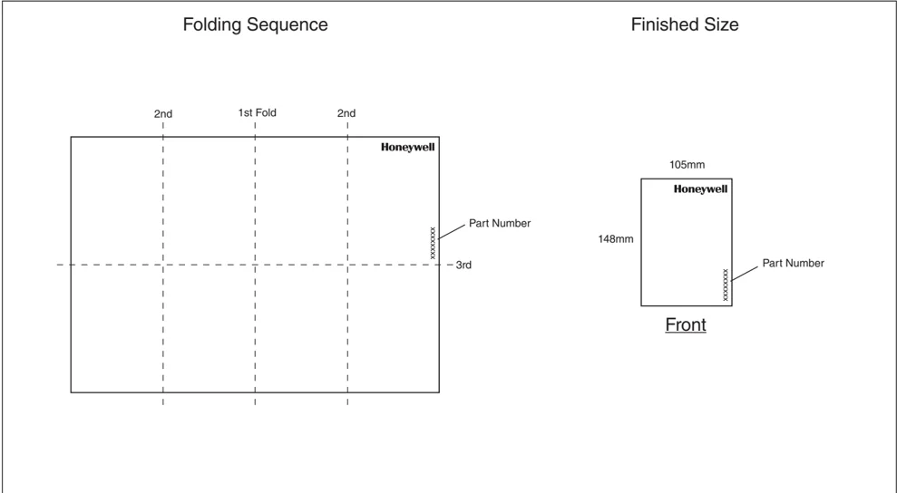
Finished Size
DO NOT INCLUDE THIS PAGE IN THE PRINTING
Installer Parameters Table:
| Parameter | Parameter No. | Factory Default Setting | Optional Setting | ||
|---|---|---|---|---|---|
| Category 1 Parameters – Programmable Thermostat Settings | |||||
| Display | Description | Display | Description | ||
| AM-PM / 24hr Display | 1:CL | 12 | 12 hr – AM/PM clock display format | 24 | 24 hr clock display format |
| Reset Time/ Temp Program | 2:rP | 1 | Time / Temperature profile set to factory default.Changes to 0 when one of the time/temp profiles are changed. | 0 | Factory Time / Temperature profile has been modifiedTo restore the factory profile set to 1 |
| Auto Summer/Winter Time Change | 3:tC | 1 | Auto Summer/Winter Time Change Enabled | 0 | Auto Summer/Winter Time Change Disabled |
| LCD Backlighting | 5:bL | 1 | Backlighting Enabled | 0 | Backlighting Disabled |
| Upper Temp Limit | 6:uL | 35 | 35°C Upper Temp. Limit | 21 to 34 | 21°C to 34°C adjustment in 1°C steps |
| Lower Temp Limit | 7:LL | 5 | 5°C Lower Temp. Limit | 5 to 21 | 5°C to 21°C adjustment in 1°C steps |
| Optimisation | 8:OP | 0 | Optimisation Disabled | 1 | Optimisation Enabled |
| Telephone Override | 9:tS | 0 | Telephone Override Disabled | 1 | Telephone Override Enabled |
| Second Sensor | 10:SS | 0 | Second Sensor Disabled | 1 or 2 | Second Sensor Enabled:1 = Outside Sensor2 = Remote Room Sensor |
| Temperature Offset | 12:tO | 0.0 | No temperature offset | -3 to +3 | -3°C to +3°C adjustment in 0.1°C steps |
| Proportional Band Width | 13:Pb | 1.5 | Proportional band of 1.5 degree | 1.6 to 3.0 | 1.6°C to 3.0°C adjustment in 0.1°C steps |
| Reset Parameters to Factory Defaults | 19:FS | 1 | All settings at factory defaultsChanges to 0 when one of the parameter is changed | 0 | Settings are as modified aboveTo restore the factory parameters set to 1 |
| Category 2 Parameters – System Settings (press PROGRAM ▶ to access this category) | |||||
| Display | Description | Display | Description | ||
| Minimum boiler ON time | 1:Ot | 1 | 1 minute minimum ON time | 2 to 5 | Selection of 2, 3, 4 or 5 minutes minimum ON time |
| Cycle Rate | 2:Cr | 6 | 6 cycles per hour (cph) | 3, 9 or 12 | Selection of 3, 9 or 12 cph |
| Electric Heat | 3:EH | 0 | Resistive Loads <3 A | 1 | Resistive loads 3 to 8 A |
| Heat/Cool Change | 4:HC | 0 | Disabled | 1 | Enabled |
| Pump Exercise | 5:PE | 0 | Pump exercise disabled | 1 | Pump exercise enabled |
Notes: Remember to always press the green OK button to confirm that you want to store your new Installer Set-Up setting. To exit the Installer Mode move the slider switch to the AUTO or MAN positions.
System Commissioning
To enter the diagnostic mode move the slider switch to the OFF position then press and hold the i button for 5 sec. The unit will enter the user settings mode. Next press and hold the i and + buttons together. The unit will hold the relay on for 5 minutes and the following information can be viewed on the display by pressing the i ▲ or ▼ buttons. : model ID, date code (WW/YY) and checksum.
CM900 Installation Guide
Programmable Room Thermostat
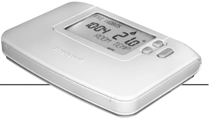
The Honeywell CM900 (CM907 or CM901) is a modern programmable room thermostat based on Honeywell’s proven programming philosophy. To further improve the ease of use, this product includes a very large LCD display with backlighting and a Dynamic Text Display to assist customers during daily use.
Installing the Thermostat
1 Find a suitable location for mounting

2 Remove from packaging
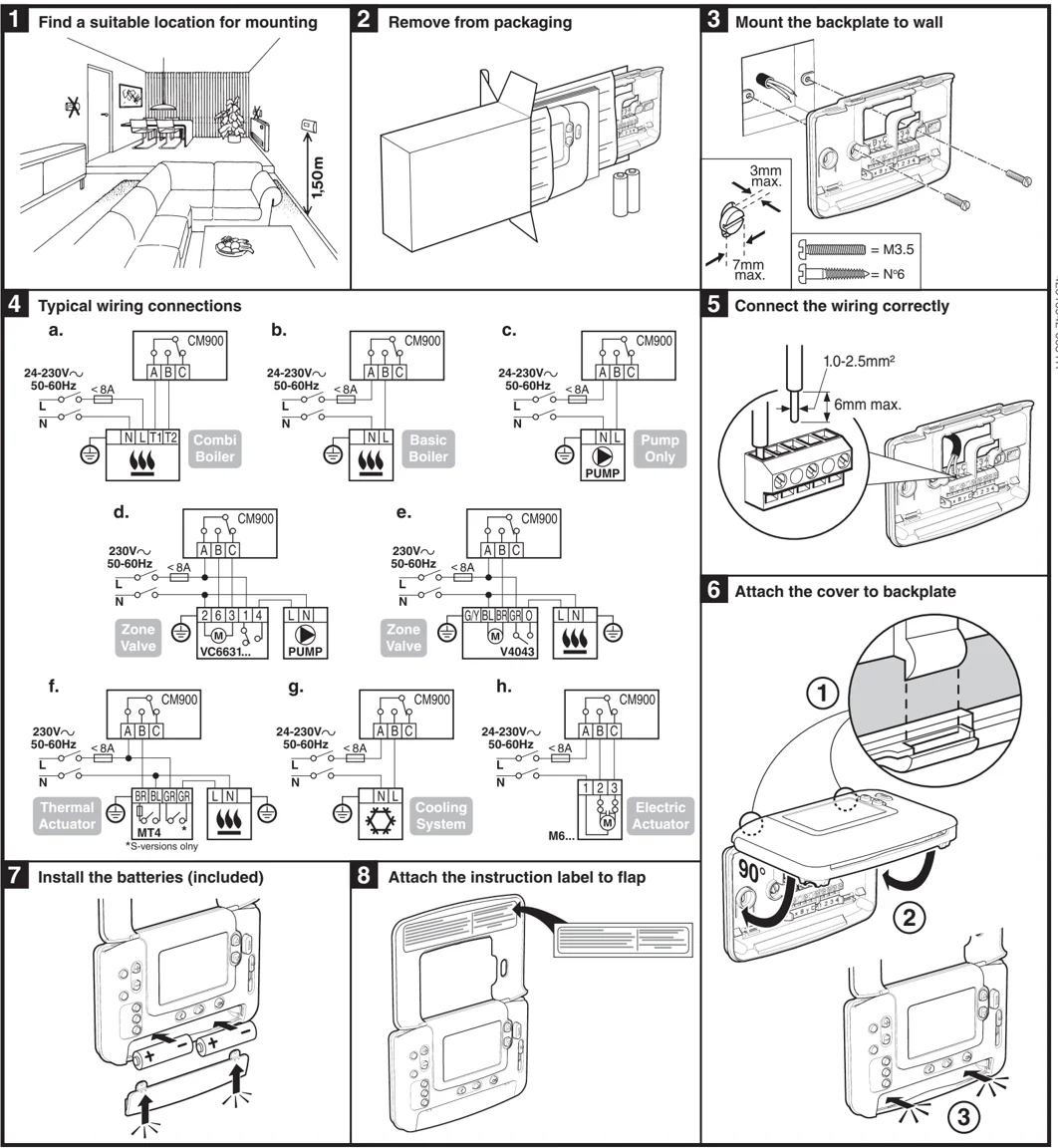
3 Mount the backplate to wall
4 Typical wiring connections
5 Connect the wiring correctly
6 Attach the cover to backplate
7 Install the batteries (included)
8 Attach the instruction label to flap
Honeywell Control Systems Ltd. Arlington Business Park, Bracknell Berkshire RG12 1EB Technical Help Desk: 08457 678999 www.honeywelluk.com
42010942-003 R1 © 2005 Honeywell International Inc.
“Manufactured for and on behalf of the Environment and Combustion Controls Division of Honeywell Technologies Sàrl, Ecublens, Route du Bois 37, Switzerland by its Authorised Representative Honeywell International Inc.”
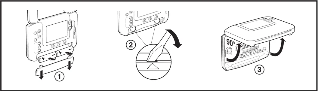
Removing the Cover
Setting-up the Thermostat
Please follow the illustrations detailed on page 1 in sequence to install the thermostat correctly, then refer to the steps below:
NOTE: For gas boiler applications, the factory system settings will not need to be changed (for other applications see section ‘Using the Thermostat for Specific Applications’ below).
To set-up the thermostat:
- Remove the battery cover and insert the batteries supplied with the unit (2 x AA LR6 Alkaline Batteries).
- Move the slider switch to the DATE position.
- Use the ⬍+⬎ or ⬍–⬎ buttons to set the correct day / month / year, pressing the green OK button to confirm.
- Use the ⬍+⬎ or ⬍–⬎ buttons to set the correct time, pressing the green OK button to confirm.
- Move the slider switch to the required operating mode (AUTO, MAN or OFF) to begin operating at the default factory settings, or move to PROG and modify the built-in heating program accordingly (see User Guide).
You can now use the ‘User Guide’ supplied with the thermostat to demonstrate how it works to the home owner.
Using the Thermostat for Specific Applications
The CM900 thermostat is a versatile controller that can be used to control many different applications. For most typical applications, like ‘wall-hung gas fired combination boiler control’ or ‘zone valve control’, no adjustments from the factory settings are required.
For other applications, like controlling an oil burner, the best system performance can be achieved by modifying selected parameters of the thermostat in installer's mode. The table below lists the most common settings used for a specific application:
| Specific Application: | Setting: | What to change: | |
|---|---|---|---|
| Cycle/Hour | Minimum ON Time | ||
| Note: All parameters listed below belong to category 2 - System Parameters (see Installer Parameters Table) | |||
| HEATING | Gas Boiler (<30kW) | 6 | 1 |
| No changes required | |||
| Oil Boiler | 3 | 4 | |
| Set 1:Ot parameter to 4Set 2:Cr parameter to 3 | |||
| Thermal Actuator | 12 | 1 | |
| Set 2:Cr parameter to 12 | |||
| Zone Valve | 6 | 1 | |
| No changes required | |||
| Electric Heating (resistive load <8A) | 12 | 1 | |
| Set 2:Cr parameter to 12Set 3:EH parameter to 1 | |||
| AIR-CONDITIONING | |||
| To enable switching between cooling and heating modes adjust parameter 4:HC in category 2 (0 = disabled, 1 = enabled). Now you can switch between these modes by pressing the ⬍▲⬎ and ⬍▼⬎ buttons together for 5 seconds in any of the product operating modes (AUTO, MAN or OFF). Explain to the end user how to switch between these modes using the ⬍▲⬎ and ⬍▼⬎ buttons and ensure the cooling program is modified as required. | |||
| Heat Pump / Air-Conditioner | 3 | 4 | |
| Set 1:Ot parameter to 4Set 2:Cr parameter to 3 | |||
| Fan Coil | 6 | 1 | |
| No changes required |
Using the Special Features of the Thermostat
| Special Feature: | Description: | To Enable/Disable This Feature: |
|---|---|---|
| Optimisation (Variable Start Time) | The thermostat will adjust the start time in the morning/afternoon so the desired temperature is reached by the start of the program period. The system will restrict the start time to a max of 2 hours. | To enable: Set parameter 8:OP (category 1) to 1. |
| Heating or Cooling Operation | This product can be used for heating or cooling applications. If you select cooling mode the control algorithm and factory default program will be modified. You can independently modify the heating and cooling profile. | To enable: Set parameter 4:HC (category 2) to 1. |
| Summer/Winter Auto time change | This feature moves time automatically on the last Sunday of March and the last Sunday of October. The feature is factory enabled. | To enable: Set parameter 3:tC (category 1) to 1. |
| Temperature Offset | If the thermostat is located in a particularly hot/cold location and cannot be moved because of wiring restrictions then the measured/displayed temperature can be adjusted by +/- 3°C. This is useful if the homeowner wants the reading to match another appliance temperature display. | Set parameter 12:tO (category 1) to the required offset value. |
| Upper/Lower Temperature Limit | The normal upper temperature limit of 35°C can be reduced to 21°C to save the homeowner energy. The normal lower limit of 5°C can be increased up to 21°C to protect inhabitants from cold. | Set parameter 6:uL (category 1) to the desired upper limit.Set parameter 7:LL (category 1) to the desired lower limit. |
Optional Accessories
| Accessory: | Description: | To Enable/Disable This Feature: |
|---|---|---|
| Outside Temperature Sensor | An Outside Temperature Sensor can be fitted to the thermostat, allowing the homeowner to display the outside temperature on the display by pressing the ⬍i⬎ button. | 1. Fit the sensor (instructions are included in the sensor package).2. Set 10:SS parameter (category 1) to 1. |
| Remote Temperature Sensor | A Remote Temperature Sensor can be fitted to the thermostat, allowing it to control the temperature from another room e.g. in commercial premises where the public may adjust keys. | 1. Fit the sensor (instructions included in the sensor package)2. Set 10:SS parameter (category 1) to 2. |
Entering the Installer Mode
-
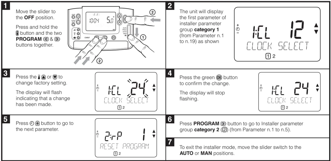
Move the slider to the OFF position.Press and hold the ⬍i⬎ button and the two PROGRAM ⬍◀⬎ & ⬍▶⬎ buttons together.
-
The unit will display the first parameter of installer parameter group category 1 (from Parameter n.1 to n.19) as shown
-
Press the ⬍▲⬎ or ⬍▼⬎ to change factory setting.The display will flash indicating that a change has been made.
-
Press the green OK button to confirm the change.The display will stop flashing.
-
Press ⬍+⬎ button to go to the next parameter.
-
Press PROGRAM ⬍▶⬎ button to go to Installer parameter group category 2 (②) (from Parameter n.1 to n.5).
-
To exit the installer mode, move the slider switch to the AUTO or MAN positions.
