Grizzly®
INDUSTRIAL, INC.
10" HEAVY-DUTY TABLE SAW
MODEL G1023 INSTRUCTION MANUAL

COPYRIGHT © 1990 BY GRIZZLY IMPORTS, INC REG #TX 3 170 579. REVISED JANUARY, 2018 (HE) WARNING: NO PORTION OF THIS MANUAL MAY BE REPRODUCED IN ANY SHAPE OR FORM WITHOUT THE WRITTEN APPROVAL OF GRIZZLY IMPORTS, INC. APRIL, 1997. PRINTED IN TAIWAN
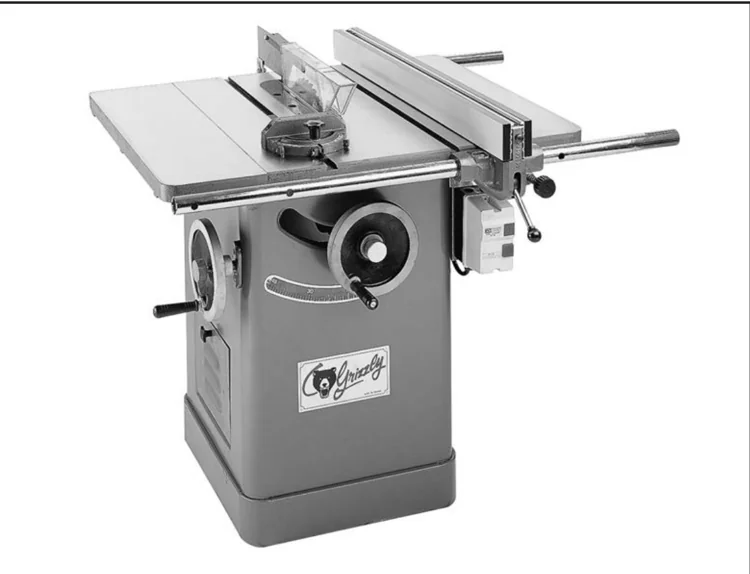
Table Of Contents
| SECTION | TITLE | PAGE |
|---|---|---|
| 1. | SAFETY INSTRUCTIONS | 2 |
| SAFETY INSTRUCTIONS FOR POWER TOOLS | 2 | |
| ADDITIONAL SAFETY INSTRUCTIONS FOR TABLE SAWS | 3 | |
| 2. | GENERAL INFORMATION | 4 |
| UNPACKING | 5 | |
| PIECE INVENTORY | 5 | |
| CLEAN UP | 6 | |
| SITE CONSIDERATIONS | 6 | |
| CIRCUIT REQUIREMENTS | 7 | |
| GROUNDING | 7 | |
| 3. | ASSEMBLY | 8 |
| BEGINNING ASSEMBLY | 8 | |
| HAND WHEELS | 8 | |
| SWITCH | 9 | |
| EXTENSION WINGS | 9-10 | |
| GUARD SUPPORT SHAFT | 10 | |
| BLADE | 11 | |
| BLADE GUARD | 11-12 | |
| FENCE RAILS | 12 | |
| FENCE | 13 | |
| TABLE INSERTS | 13-14 | |
| 4. | ADJUSTMENTS | 15 |
| MITER TO BLADE | 15 | |
| 90° POSITIVE STOP | 16 | |
| 45° POSITIVE STOP | 17 | |
| ANGLE POINTER | 18 | |
| MITER GAUGE | 18 | |
| FENCE | 19-20 | |
| BLADE ALIGNMENT | 20 | |
| 5. | OPERATIONS | 21 |
| PRE-RUN CHECK | 21 | |
| TEST RUN | 21 | |
| BLADE SELECTION | 22-23 | |
| CROSSCUTTING | 23 | |
| RIPPING | 24 | |
| 6. | MAINTENANCE | 25 |
| TABLE AND WINGS | 25 | |
| V-BELT | 25-26 | |
| LUBRICATION | 26 | |
| 7. | CLOSURE | 27 |
| PARTS BREAKDOWNS AND LISTS | 28-33 | |
| MACHINE DATA | 34 | |
| TROUBLESHOOTING | 35 | |
| WARRANTY AND RETURNS | 36 | |
| -STICK PATTERN | 37 |
-2- G1023 Heavy-Duty Table Saw
SECTION 1: SAFETY
WARNING: For Your Own Safety Read Instruction Manual Before Operating Saw
- Wear eye protection.
- Use saw-blade guard and spreader for every operation for which it can be used, including all through sawing.
- Keep hands out of the line of saw blade.
- Use a push-stick when required.
- Pay particular attention to instructions on reducing risk of kickback.
- Do not perform any operation freehand.
- Never reach around or over saw blade.
Safety Instructions For Power Tools
These safety rules cannot cover every situation in a woodshop. Consider your conditions when setting up or operating your table saw.
- KEEP GUARDS IN PLACE and in working order.
- REMOVE ADJUSTING KEYS AND WRENCHES. Form habit of checking to see that keys and adjusting wrenches are removed from tool before turning on.
- KEEP WORK AREA CLEAN. Cluttered areas and benches invite accidents.
- DON'T USE IN DANGEROUS ENVIRONMENT. Don't use power tools in damp or wet locations, or expose them to rain. Keep work area well lighted.
- KEEP CHILDREN AWAY. All visitors should be kept a safe distance from work area.
- MAKE WORK SHOP KID PROOF with padlocks, master switches, or by removing starter keys.
- DON'T FORCE TOOL. It will do the job better and safer at the rate for which it was designed.
- USE RIGHT TOOL. Don't force tool or attachment to do a job for which it was not designed.
- USE PROPER EXTENSION CORD. Make sure your extension cord is in good condition. When using an extension cord, be sure it is rated Hard Service (grade S) or better. Conductor size must be 16 A.W.G. for cords up to 100 feet in length. An undersized cord will cause a drop in line voltage resulting in loss of power and overheating. Your extension cord must also contain a ground wire and plug pin. Always repair or replace extension cords if they become damaged. Minimum Gage for extension cord:
| 16 A.W.G. | 50ft |
|---|---|
| 16 A.W.G. | 100ft |
| 14 A.W.G. | 200ft |
| 12 A.W.G. | 300ft |
- WEAR PROPER APPAREL Do not wear loose clothing, gloves, neckties, rings, bracelets, or other jewelry which may get caught in moving parts. Non-slip footwear is recommended. Wear protective hair covering to contain long hair.
- ALWAYS USE SAFETY GLASSES. Also use face or dust mask if cutting operation is dusty. Everyday eyeglasses only have impact resistant lenses, they are NOT safety glasses.
-
SECURE WORK. Use clamps or a vise to hold work when practical. It’s safer than using your hand and frees both hands to operate tool.
-
DON’T OVERREACH. Keep proper footing and balance at all times.
-
MAINTAIN TOOLS WITH CARE. Keep tools sharp and clean for best and safest performance. Follow instructions for lubricating and changing accessories.
-
DISCONNECT TOOLS before servicing and changing accessories, such as blades, bits, cutters, and the like.
-
REDUCE THE RISK OF UNINTENTIONAL STARTING. Make sure switch is in off position before plugging in.
-
USE RECOMMENDED ACCESSORIES. Consult the owner’s manual for recommended accessories. The use of improper accessories may cause risk of injury.
-
CHECK DAMAGED PARTS. Before further use of the tool, a guard or other part that is damaged should be carefully checked to determine that it will operate properly and perform its intended function - check for alignment of moving parts, binding of moving parts, breakage of parts, mounting, and any other conditions that may affect its operation. A guard or other part that is damaged should be properly repaired or replaced.
-
DIRECTION OF FEED. Feed work into a blade or cutter against the direction of rotation of the blade or cutter only.
-
NEVER LEAVE TOOL RUNNING UNATTENDED. TURN POWER OFF. Don’t leave tool until it comes to a complete stop.
Additional Safety Instructions For Table Saws
-
ALWAYS use guard, splitter and anti-kickback fingers on all "through-sawing" operations. Through-sawing operations are those when the blade cuts completely through the work- piece as in ripping or cross cutting.
-
ALWAYS hold the work firmly against the miter gauge or fence.
-
ALWAYS use a push-stick for ripping narrow stock. Refer to ripping applications on Page 23 of this manual, and Page 37 where push- stick use is covered in detail.
-
NEVER perform any operation "free-hand" which means using only your hands to support or guide the workpiece. Always use either the fence or the miter gauge to position and guide the work.
-
NEVER stand or have any part of your body in line with the path of the saw blade.
-
NEVER reach behind or over the blade with either hand for any reason.
-
MOVE the rip fence out of the way when cross cutting.
-
NEVER use the fence as a cut-off gauge when cross cutting.
-
NEVER attempt to free a stalled saw blade without first turning the saw OFF.
-
PROVIDE adequate support to the rear and sides of the saw table for wide or long workpieces.
-
AVOID KICKBACKS (work thrown back toward you) by keeping blade sharp, keeping rip fence parallel to the saw blade, keeping splitter and anti-kickback fingers and guard in place and operating, by not releasing work before it is pushed all the way past the saw blade, and by not ripping work that is twisted or warped or does not have a straight edge to guide along the fence.
-
AVOID awkward operations and hand positions where a sudden slip could cause your hand to move into the blade.
-4- G1023 Heavy-Duty Table Saw
SECTION 2: GENERAL
Grizzly Imports, Inc. is proud to offer the Model G1023 10" Heavy-Duty Table Saw. This model G1023 is a part of Grizzly's growing family of fine woodworking and metalworking machinery. When used according to the guidelines stated in this manual, you can expect years of trouble-free, enjoyable operation.
The Model G1023 is a cabinet-type table saw intended for heavy-duty professional use. This saw is equipped with cast-iron extension wings, regular and dado blade table inserts, table T-Slots, cast iron miter gauge, a rip fence and a blade guard. The heart of the saw is a powerful 3 H.P., 3450 rpm, capacitor start motor with magnetic push-button switch. All running parts operate on shielded ball bearings and require no maintenance for the life of the bearings. We also offer many accessories for this table saw including blades, extension rails outfeed rollers and a mobile base. Please refer to our current catalog for prices and ordering information.
We are also pleased to provide this manual with the Model G1023. It was written to guide you through assembly, review safety considerations, and cover general operating procedures. It represents our latest effort to produce the best documentation possible. If you have any criticisms that you feel we should address in our next printing, please write to us at the Bellingham, WA address at the end of this section.
Most important, we stand behind our machines. We have an excellent service departments at your disposal should the need arise. If you have any service questions or parts requests, please call or write to us at the location listed below.
Grizzly Imports, Inc. 2406 Reach Road Williamsport, PA 17701 Phone:(717) 326-3806 Fax:(800) 438-5901 E-Mail: Grizzlytec@aol.com Web Site: http://www.grizzlyimports.com
To comment on this manual write to:
Grizzly Imports, Inc. % Technical Documentation P.O. Box 2069 Bellingham, WA 98227
To operate this or any power tool safely and efficiently, it is essential to become as familiar with it as possible. The time you invest before you begin to use your Model G1023 will be time well spent. DO NOT operate this machine until you are completely familiar with the contents of this manual.
Unpacking
The Model G1023 is shipped from the manufacturer in a carefully packed carton. If you discover the machine is damaged after you've signed for delivery, please call Customer Service immediately for advice.
Save the containers and all packing materials for possible inspection by the carrier or its agent. Otherwise filing a freight claim can be difficult.
Caution: The Model G1023 is a heavy machine (425 lbs. shipping weight). DO NOT over-exert yourself while unpacking or moving your machine – get assistance. In the event that your table saw must be moved up or down a flight of stairs, be sure that the stairs are capable of supporting the combined weight of people and the machine.
When you are completely satisfied with the condition of your shipment, you should inventory its parts.
-6-
Piece Inventory
After all the parts have been removed from the carton, you should have:
- Table Saw Unit
- Miter Gauge
- Extension Wings (2)
- Fence Rails
- Adhesive Scale For Fence
- Fence Assembly
- Splitter/Guard Assembly
- Bolt Bag
Contents of bolt bag:
3/4" - 16 x 1-1/4" Hex Bolts (6) 3/4" Lock Washers (6) 3/4" - 16 x 1" Cap Screws (4) Hex Nuts 3/8"-16 (4) 3/8" Flat Washers(4)
In the event that any non-proprietary parts are missing (e.g. a nut or a washer), we would be glad to replace them, or, for the sake of expediency, replacements can be obtained at your local hardware store.

Clean up
The table and other unpainted parts of the Model G1023 are coated with a waxy oil that protects them from corrosion during shipment. Remove the protective coating with mineral spirits and paper towels. Do not use gasoline or other petroleum based solvents because of their extremely low flash points. Do not use chlorine-based solvents – if you happen to splash some onto a painted surface, you’ll ruin the finish.
WARNING!
Follow the safety rules listed below when working with solvents:
- Read and follow all directions and warnings on the solvent label.
- Work only in a well ventilated area.
- Do not work near any type of open flame (e.g., pilot lights, kerosene heaters, and so on).
- DO NOT smoke while working with flammable material.
- Paper towels from the cleaning process are extremely combustible. Dispose of waste towels so they do not create a fire hazard.
G1023 Heavy-Duty Table Saw
Site Considerations
- Floor Load: Your Model G1023 Table Saw represents a large weight load in a small footprint. Most commercial floors are suitable for the Model G1023. Some residential floors may require additional bracing to support both machine and operator.
- Working Clearances: Consider existing and anticipated needs, size of material to be processed through each machine, and space for auxiliary stands, work tables or other machinery when establishing a location for your Table Saw.
- Lighting and Outlets: Lighting should be bright enough to eliminate shadow and prevent eye strain. Electrical circuits should be dedicated or large enough to handle amperage requirements. Outlets should be located near each machine so power or extension cords are clear of high-traffic areas. Observe local electrical codes for proper installation of new lighting, outlets, or circuits.
Circuit Requirements
The Model G1023 Table Saw has one 3 HP motor. It has been pre-wired to operate at 220V, single phase operation and cannot be operated at 110V. The Model G1023 motor will safely draw about 18 amps at 220V. If you operate the table saw on any circuit that is already close to its capacity, it might blow a fuse or trip a circuit breaker. However, if an unusual load does not exist, and power failure still occurs, have the circuit inspected by a qualified electrician.
Circuit breakers/fuses: A 30 amp circuit breaker or fuse should be used with a 220V dedicated circuit. The general rule is to use the lightest breaker or fuse that will hold under regular loads. Circuit breakers or fuses that are rated higher may not adequately protect the motor.
The Model G1023 is not equipped with a plug. It will be necessary to connect a plug that is suitable for your 220V receptacle. Figure 1.
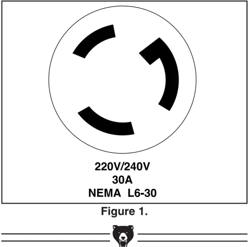
220V/240V 30A NEMA L6-30
Figure 1.
Grounding
This equipment must be grounded. Please ensure that the Model G1023 is continuously grounded from the motor to the machine frame and then to a known ground. Verify that any existing electrical outlet and circuit you intend to plug into is actually grounded. If it is not, it will be necessary to run a separate 12 A.W.G. copper grounding wire from the outlet to a known ground. Under no circumstances should the grounding pin from any three-pronged plug be removed.
CAUTION: Be sure that your particular electrical configuration complies with local and state codes. The best way to ensure compliance is to check with your local municipality or licensed electrician.

SECTION 3: ASSEMBLY
Beginning Assembly
Most of your Model G1023 Table Saw has been assembled at the factory, but some parts must be assembled or installed after delivery. We have organized the assembly process into steps. Please follow along in the order presented here.
Note: All die-cut metal parts have a sharp edge (called “flashing”) on them after they are formed. This is removed at the factory. Sometimes, though, a bit of flashing might escape inspection. Please examine the edges of all metal parts before handling them.
TOOLS REQUIRED: A high quality square and long straightedge plus common hand tools are necessary to assemble this machine. You will need a set of open and closed ended metric wrenches, a flat tipped screwdriver, Phillips screwdriver, dead blow hammer, and a 6" or 8" adjustable wrench.
Hand Wheels
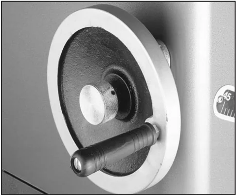
The handle on the arbor tilting hand wheel has been installed backward for shipping.
Unscrew it and then reinstall it in the correct position. Figure 2.


Switch
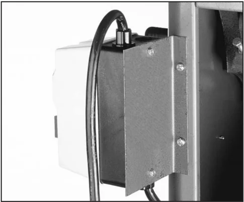
The magnetic switch comes prewired to the motor. However, you must mount the switch to the table saw body before it can be used. A bracket with screws to attach it is provided.
Extension Wings
Inspect the extension wings for burrs or foreign material that may inhibit assembly. The mating edges of the wings and table must be clean, smooth, and flat. Use a wire brush or file if necessary to clean up the edges. It is possible to attach the extension wings to the table by yourself, but it is easier if someone else holds the wing in place while you insert the bolts.
- Attach each wing to the table using the six 3/8" - 16 x 1 1/4" Hex Head Bolts and 3/8" Flat Washers provided. Get the wings reasonably flush with the table. Do not tighten the bolts.
- Align the top of the wing flush with the table top directly above the front bolt and tighten the front bolt. The front surface of the extension wing should also be flush with the front surface of the table.
- Raise or lower the rear of the extension wing until the middle of the wing is flush with the table top. Tighten the middle bolt.
- Raise or lower the rear of the wing until the wing and table are flush. Tighten the bolt. Any adjustment at this point should be very slight.
- Re-check flushness at the front bolt and re-adjust if necessary.
- Repeat steps 2-4 for the other extension wing.
- Now, check the alignment of the table and both wings with a straight edge. The straight-edge should run flat across both wings and the table top. Figure 4. If the straightedge contacts both wings and the table evenly, you are finished with this section. If it does not, continue to step 8.

Guard Support Shaft
Install the guard support shaft before installing the blade. This will eliminate the risk of accidentally touching the sharp edges of the blade while working inside the saw cabinet.
- Push the threaded end of the shaft through the hole in the back of the saw until the shoulder on the shaft stops it.
- Secure the shaft with the hex nut provided. Figure 6.
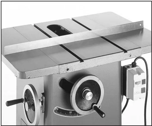
Figure 4.
-
If the wing tilts down, remove the wing and stick layers of masking tape under each bolt near the bottom edge. Re-install the wing and check the flushness again.
-
If the wing tilts up, remove the wing and stick layers of masking tape over each bolt near the top edge. Re-install the wing and check the flushness again. Figure 5.
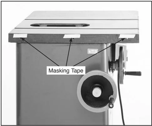
Masking Tape
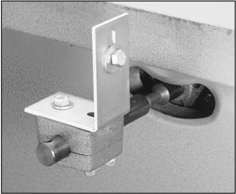


Blade
The Model G1023 is not supplied with a blade. For a selection of blades, including dado sets, refer to the Grizzly catalog for selection, price and ordering information. To install the blade:
- Remove the arbor nut and outside arbor flange from inside the blade cavity. Figure 7. The arbor nut and arbor are left hand threaded.
- Slide the saw blade over the arbor. Ensure that the blade teeth point toward you when standing at the front of the saw.
- Use the arbor wrench provided with the saw to tighten the arbor nut and secure the blade. Wedge a block of wood in the teeth to keep the blade from turning when tightening the nut. Be sure the arbor flanges are on either side of the blade.
- When removing the blade, use the same block of wood to wedge the blade and the nut will come off easily.
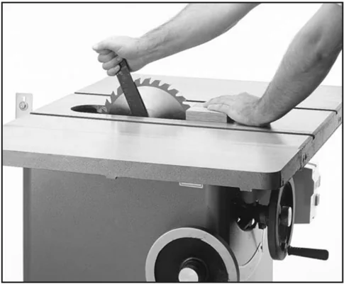
Figure 7.
Blade Guard
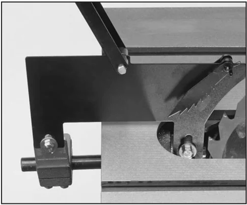
- Slip the blade guard/splitter over the mounting bolts. Figure 8. The washers should be between the bolt head and the slots. Tighten the bolts to secure the blade guard/splitter.
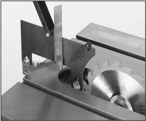
- Set a combination square against the face of the guard. Slightly rotate the rear bracket to adjust the face of the blade guard perpendicular to the table top. Figure 9.
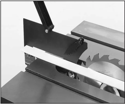
- Next, set a straightedge against the face of the saw blade and the blade guard. Figure 10. Loosen and adjust the rear blade guard bracket to set the alignment at the rear, then add washers as necessary between the splitter and the front mounting bracket to gain adjustment in the front.
- Recheck guard alignment to the blade and to the table top. Adjust as necessary and tighten down all the bolts before use.
Fence Rails
The rails should extend to the right of the saw and are attached to the table top with cap screws and dished spacers. The rails come packed in a separate box. To mount the rails:
-
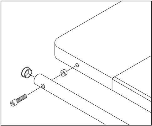
Attach the front and rear rails to the drilled and tapped holes on each extension wing. Figure 11. Be sure that the rail with the scale is mounted on the front side of the machine, with the markings facing up.
-
Insert the round, plastic plugs into the ends of each rail.


Fence
To mount the fence:
- Thread the plastic knob onto the lock handle.
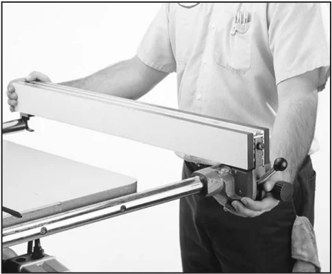
Figure 12.
- The fence will require further adjustments covered in Section 3, page 19-20.
Table Inserts
Your table saw comes with two table inserts. One is for standard blades and the other is for dado blades. Figure 13.

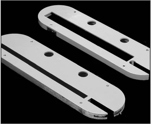
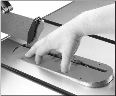
- Install the table insert by putting your fingers into the finger holes of the insert and lifting the front to install it as shown in Figure 14. There is a small pin at the back of the insert which fits into a hole in the back edge of the blade cavity. Note: The blade will not be exactly centered in the insert slot. This is normal. This positioning allows the blade to tilt a full 45° without hitting the insert.
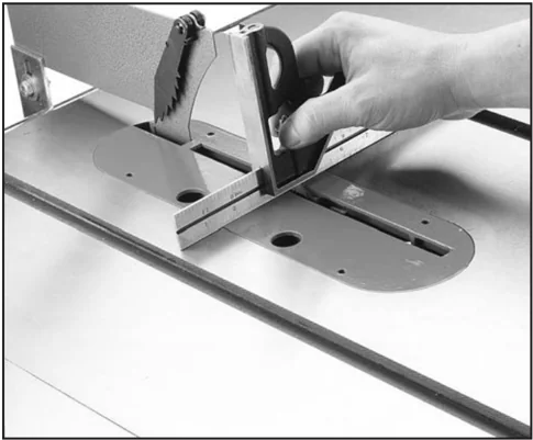
- Make the insert flush with the table top by adjusting the four setscrews in the insert. Check flushness with a straight edge. Figure 15.
-
A drop of glue or Loctite® on the threads of the setscrews will keep the setting from changing.
-
If the blade hits the edge of the insert when raised, the blade is out of alignment. See Section 3 page 19.

SECTION 4: ADJUSTMENTS
Miter Slot to Blade
Your table saw will give the best results if the miter slot and rip fence are adjusted parallel to the blade. If they are not exactly parallel, your cuts and finished work will be lower in quality. Take the time to adjust your table saw properly. A few minutes now will be time well spent. CAUTION: Ensure that the table saw is unplugged from its power source before making any adjustments. To check and adjust parallelism between miter slot and blade:
- Use a piece of tape to mark the blade in the gullet between two (2) teeth closest to the table.
- Use a steel rule to measure the distance from the mark on the blade to the edge of the miter slot. Figure 16.
- Rotate the blade 180°.
- Measure the distance from the mark on the blade to the edge of the miter slot. Figure 17.
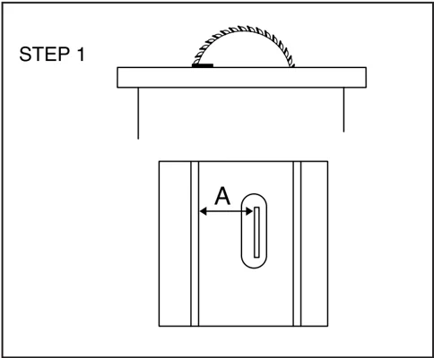
Figure 16.
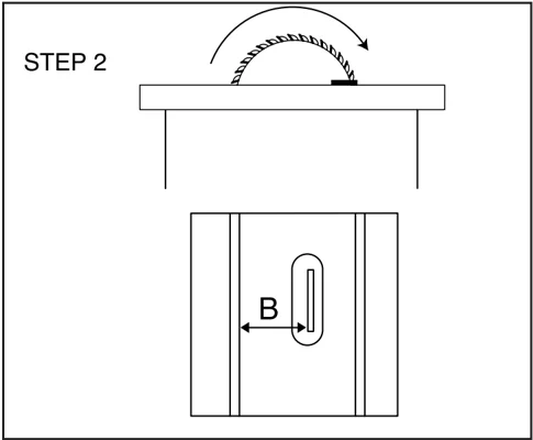
Figure 17.
- The difference between distance A and distance B must be equal to or less than 1/64".
- If the difference is greater than 1/64", loosen the four (4) table mounting bolts and adjust the table slightly. Figure 18. Repeat steps 1-5 until satisfactory. Do not forget to tighten the table mounting bolts when finished.
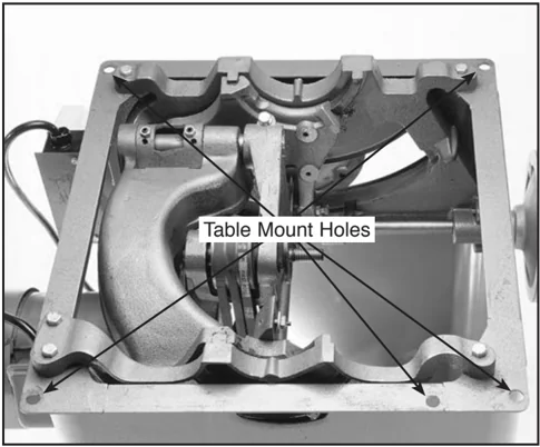
90° Positive Stop
Your table saw will be easier to use and produce more predictable results if it is adjusted correctly. Next to parallelism, the 90° positive stop is perhaps the most important adjustment point on the saw. To adjust the 90° positive stop bolt:
- Turn the arbor tilting handwheel (the one on the left side of the saw) until the 90° positive stop limits movement.
- Check the angle of the blade to the table with a high quality square. Figure 19. If the blade is 90° to the table, you are finished. If the blade is not exactly 90° to the table, proceed to the next steps.
- Angle the blade toward 45° to allow access to the stop bolt.
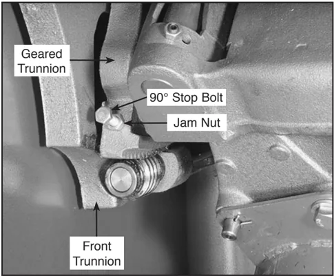
- Locate the stop bolt on the geared trunnion inside the cabinet. Figures 20.
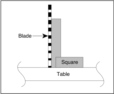
Figure 19.
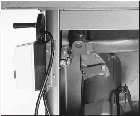
Figure 20. Location for 90° positive stop.
- Loosen the jam nut and thread the stop bolt in or out not more than a half turn. Figure 21.
- Tighten the jam nut and tilt the blade back to 90°. Check the angle of the blade with the square.
- Repeat steps 3-6 as necessary.
45° Positive Stop
To adjust the 45° positive stop bolt:
- Turn the arbor tilting handwheel (the one on the left side of the saw) until the 45° positive stop limits movement.
- Check the angle of the blade to the table with a high quality angle gauge. Figure 22. If the blade is 45° to the table, you are finished. If the blade is not exactly 45° to the table, proceed to the steps below.
- Angle the blade toward 90° to allow access to the stop bolt.
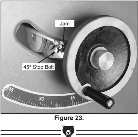
- Locate the stop bolt on the geared trunnion inside the cabinet. It is accessed through the hole in the side of the cabinet behind the blade height hand wheel. Figure 23.
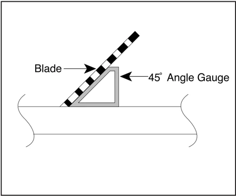
Figure 22.
- Loosen the jam nut behind the 45° stop bolt. Tighten or loosen the stop bolt to adjust the stopping position of the arbor. Tighten the jam nut.
- Tilt the blade until the 45° stop bolt prohibits movement. Check the angle of the blade.
- Repeat steps 3-6 as necessary.
-18- G1023 Heavy-Duty Table Saw
Angle Pointer
Once the positive stops have been set, the angle pointer will require adjusting. To adjust the angle pointer:
- The angle pointer is located behind the arbor height hand wheel. Figure 24. (hand wheel removed for clarity)
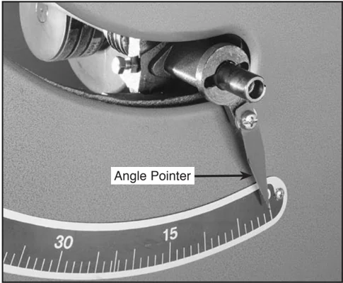
Figure 24.
- Turn the arbor tilting hand wheel until it stops on the 90° positive stop.
- Loosen the pointer and set it to "0" on scale. Tighten the screw.
- Turn the arbor tilting hand wheel until it stops on the 45° stop.
- If the pointer is set on 45°, skip to the next adjustment. If it does not point to 45°, repeat steps 2-4 until the pointer is adjusted correctly.
Miter Gauge
To adjust the miter gauge so it is perpendicular to the saw blade:
- Loosen the lock knob on the miter gauge and place a square against the face of the miter body and the blade.
- Adjust the miter body until there is no space between the square and the blade. Tighten the lock knob.
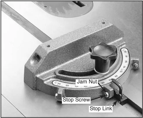
- With the stop link in the up position, loosen the jam nut and adjust the stop screw until it is seated against the stop link. Figure 25.
- Now loosen the setscrew on the left front side of the miter bar, adjust the pointer to 90° and retighten the setscrew.
- To adjust to 45°, follow steps 1-4 using an adjustable square set to 45°.
- After rotating the miter body from 45° to 90° and back a few times, double check your adjustments at both angles to assure that you have accurately set your miter gauge.


Fence
The fence must engage and square up on the front rail before the rear clamp engages the back rail. In essence, the rear clamp should act as a secondary mechanism for maintaining fence position. When adjusted correctly, the lever lock should only begin to apply pressure on the back rail over the last one third of its stroke. To adjust the fence:
- First, make sure the front clamp is engaging the front tube with the lock handle at one half its throw. If the front clamp requires adjustment, loosen the check nut. Figure 26. Turn the adjusting bolt in if the front clamp is too far from the tube, out if it is too close.
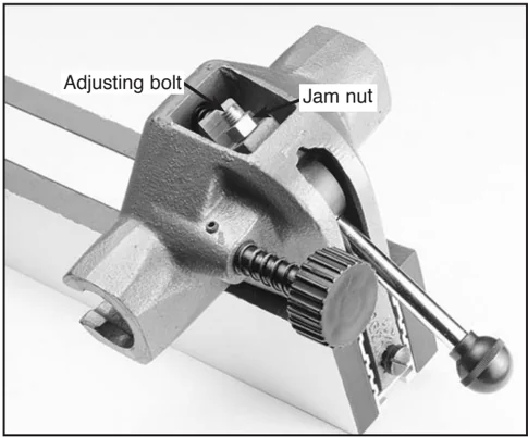
Figure 26.
-
Now slide the fence along the rail until it is aligned with the edge of the miter slot. Lock the fence down.
-
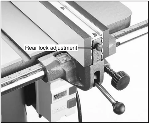
With the fence in the locked position, loosen the rear lock adjustment (the slotted screw on the front of the fence) until the rear locking lever ceases to engage the rear rail. Figure 27.
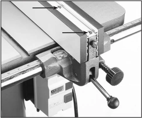
- Loosen the adjustment bolts at the top of the fence. Figure 28. move the straight portion of the fence until it is parallel with the miter slot from front to back. Tighten the bolts.
-
Loosen the locking lever until it is approximately two-thirds engaged. Tighten the rear adjusting screw until the rear clamp just touches the back rail.
-
Loosen the locking lever and slide the fence along the rail. Return the fence to its position at the edge of the miter slot and slowly apply pressure to the lever. If adjustments are correct, the fence should square itself before the rear clamp engages. If the rear clamp engages before the fence is squared, loosen the screw one quarter turn and re-test.
-
Once the fence is adjusted, check the pointer and adjust if necessary. Figure 29.
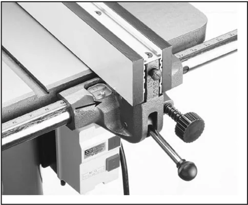
Figure 29.
Blade Alignment
The blade position can be adjusted slightly in case it contacts the table insert when raised. To adjust the blade position:
-
Remove the table and wings and set them aside.
-
Loosen the blade adjustment bolt. Figure 30.
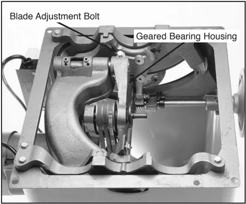
Figure 30.
-
Shift the geared bearing housing in the appropriate direction. WARNING: This adjustment should not exceed 1/16". Over adjustment will cause the blade to hit internal parts of the saw.
-
Place the blade on the arbor and finger tighten the arbor nut. Check that the blade does not contact any internal parts.
-
Replace the table, wings, and insert. Tighten securely.
-
If the blade is still touching the insert, repeat steps 1-6. CHECK ALL OTHER ADJUSTMENTS.


SECTION 5: OPERATIONS
Pre-Run Check
Before you begin to use your model G1023 Table Saw, you should give it a thorough inspection. While making your inspection, ask yourself the following questions:
- Are all the fasteners tight?
- Is the blade mounted correctly and securely?
- Is the saw stable?
- Is it wired properly?
- Is your electrical system properly configured?
- Have you checked your material for obvious defects?
- Are the V-belts properly tensioned and the pulleys properly aligned?
- Is the guard assembly installed and functional?
Test run
The table saw is one of the most valuable tools in the woodshop because it performs its duties so well. It is primarily intended to rip and crosscut and we will describe those operations in the following sections. For other uses, we suggest consulting a book dedicated to the table saw. Many are available through the Grizzly catalog.
- Face the table saw and stand to the left of the blade path.
- With one finger on the “Start” button and one finger on the “Stop” button, turn the saw on. Be ready to turn it off in case of mishap.
- Watch and listen to the saw. Note whether there are any unusual sounds or excessive vibrations.
- If ANYTHING appears abnormal, immediately turn off the saw and fix the problem. If a problem exists that is beyond the scope of this manual, call the appropriate service department.
- If the saw is behaving normally, turn it off and prepare to make a cut according to the instructions outlined in the following sections.
Blade Selection
Choosing the correct blade for the job is essential for the safe and efficient use of your table saw. Ignoring this important step could result in damage to the saw and serious injury to the operator. Documented below are the most common saw blades and their uses.
This section on blade selection is by no means comprehensive. Always follow the saw blade manufacturer's recommendations to ensure safe and efficient operation of your table saw.
Ripping Blade Features:
- Best for cutting with the grain
- 20-40 teeth
- Flat-top ground tooth profile
- Large gullets for large chip removal
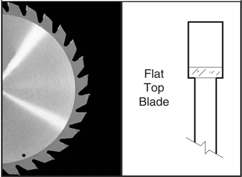
Flat Top Blade
Figure 31.
Crosscut Blade Features:
- Best for cutting across the grain
- 60-80 teeth
- Alternate top bevel tooth profile
- Small hook angle and a shallow gullet
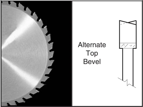
Alternate Top Bevel
Figure 32.
Combination Blade Features:
- Designed to cut both with and across grain
- 40-50 teeth
- Alternate top bevel and flat, or alternate top bevel and raker tooth profile
- Teeth are arranged in groups
- Gullets are small and shallow (similar to a cross-cut blade), then large and deep (similar to a ripping blade
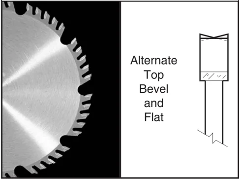
Alternate Top Bevel and Flat
Laminate Blade Features:
- Best for cutting plywood or veneer
- 40-80 teeth
- Triple chip tooth profile
- Very shallow gullet
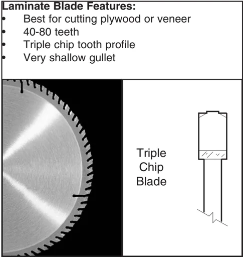
Triple Chip Blade
Figure 34.
-
Thin-kerf: Most types of saw blades are available in a thin-kerf style. Used primarily to minimize stock wastage. It is recommended thin-kerf blades be used in conjunction with a blade stabilizer to reduce blade wobble. Note: Most blade guards/splitters are thicker than most thin-kerf blades. Make sure the stock will pass by the guard/splitter before beginning a cut.
-
Dado Blades: There are two types of dado blades: stack and wobble. Stack dadoes are expensive and time consuming to set up but leave a clean and smooth finish. Stack dadoes are used for fine furniture and cabinet making. Wobble dadoes are inexpensive and easy to set up, but leave a rough finish.
This section on Blade Selection is by no means comprehensive. Always follow the saw blade manufacturer's recommendations to assure safe and efficient operation of your table saw. 24
Crosscutting
Crosscutting means cutting across the grain of the wood. In wood products without grain (i.e. MDF, particleboard) it simply means cutting across the width of the stock.
Crosscuts are made with the miter gauge. There are two miter gauge slots in the table top. Use the one that works best for the piece being crosscut. To make a crosscut using the miter gauge:
- Inspect the board for soundness. You do not necessarily need a square edge to crosscut with accuracy.
- Move the rip fence completely out of the way.
- Turn on the saw and allow it to come to full speed.
- Hold the workpiece firmly against the face of the miter gauge and ease it into the blade. Figure 36.
- Turn off the saw and allow the blade to come to a full stop.
-24- G1023 Heavy-Duty Table Saw


Ripping
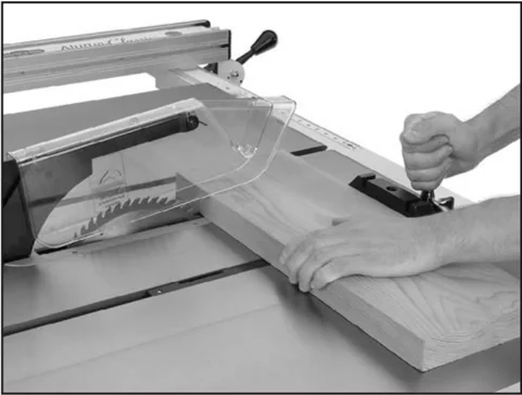
Ripping means to cut with the grain of the wood. In other materials such as MDF or plywood, ripping simply means to cut lengthwise. To rip a board:
- Inspect the board for soundness. You will need a straight edge to rip with accuracy. Your work piece may need to be jointed flat before attempting to cut on the table saw.
- Set rip fence to the desired distance from the blade. IF YOU ARE MAKING NARROW CUTS, USE A PUSH-STICK. It is unsafe to put your hands close to the blade. A push-stick pattern has been included in this manual on Page 37. Use them to hold the workpiece against the table and fence and push the workpiece fully. past the blade. When a small width is to be ripped and a push-stick cannot be safely put between the blade and rip fence, rip a larger piece to obtain the desired piece.
- Turn on the saw and allow it to reach full speed.
- Place the trued edge of the board against the rip fence.
- Feed the workpiece slowly and evenly into the blade. Figure 35. STAND OUT OF THE LINE OF POTENTIAL KICKBACK. HOLD THE WORKPIECE FIRMLY AGAINST THE FENCE AND TABLE. DO NOT ALLOW YOUR FINGERS TO GET CLOSE TO THE BLADE! DO NOT REACH OVER THE BLADE TO OFF-LOAD THE WORKPIECE.

SECTION 6: MAINTENANCE
Table and Wings
Keeping your table and wings slippery makes it easier to slide your wood when making cuts. We recommend the following types of products:
- Carnauba wax. First clean the table top thoroughly and apply a thin layer.
- Talcum powder. Clean the table and sprinkle the table with it. Rub it in with a hard felt pad such as a school blackboard eraser. The talc will fill the pores of the iron and act as a rust inhibitor.
- Coat the table surface with any number of cast iron table dressing sprays. These act as a rust and friction inhibitor and are designed especially for woodworking equipment.
Do not use paraffin or similar waxes because they leave residues and create more friction instead of less friction. Do not use silicon based lubricants. They can rub off onto the wood and prevent it from taking stains and finishes properly.
V-Belt
To ensure optimum power transmission from the motor to the blade, the V-belts must be in good condition and operate under proper tension. When replacing V-belts, it is important to replace all three at the same time-even if they do not all appear worn. Even power transmission will be ensured.
Belt tension should be checked at least every 3 months: more often if using the table saw intensively.
The V-belts are accessed through the cavity on the right side of the saw. They link the arbor and motor pulleys. To check V-belt tension:
- Squeeze the center of each V-belt.
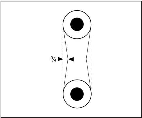
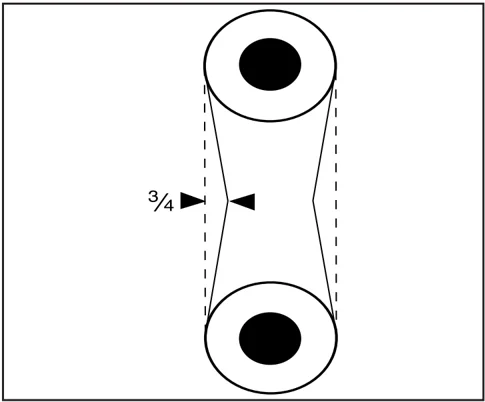
- Note the amount of deflection. Deflection should be approximately 3/4". Figure 37.

To adjust V-belt tension:
- Loosen the motor mount bolt. Figure 38.
- Shift the motor up or down to increase or decrease the V-belt tension. Tighten the motor mount bolt.
- Check the V-belt tension again. Ensure that the motor pulley and arbor pulley are lined up.
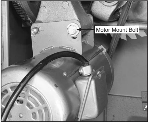
Figure 38.
To replace the V-belts:
- Remove the blade.
- Adjust the arbor so it is down all the way and in the straight up position.
- Loosen the motor mount bolt. Prop the motor up with a board so the V-Belts stay loose on the pulleys.
- Pull off the old V-belts and replace them with new ones. Have the number from the belt ready when calling the service department for replacements.
- Remove the board and adjust the V-belt tension.
- Tighten the motor mount bolt.
Lubrication
The shielded ball bearings in the motor and throughout most of the model G1023 require no further lubrication during their lifetime. When they do wear out, replacements can be obtained through the Grizzly Parts Department.
Your saw requires lubrication in several other locations, however. Lubricate the areas indicated below every 12 months.
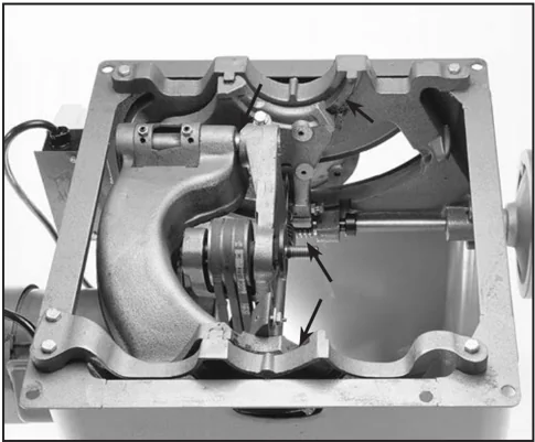
- Blade angling trunnions. These should be lubricated with 6 or 7 drops of light machine oil.
- Blade height trunnion. This should also be lubricated with 6 or 7 drops of light machine oil.
- The two (2) worm gears should be lubricated with a automotive wheel bearing grease. The blade angle worm gear is not shown in Figure 39.
These points can be reached by removing the table. Check all adjustments when finished lubricating.


SECTION 7: CLOSURE
The following pages contain general machine data, troubleshooting guide, parts diagram, parts list and Warranty/Return information for your Model G1023 Table Saw.
If you need parts or help in assembling your machine, or if you need operational information, we encourage you to call the appropriate regional Service Department. Our trained service technicians will be glad to help you.
If you have comments dealing specifically with this manual, please write to our Bellingham, Washington location using the address in the Introduction. The specifications, drawings, and photographs illustrated in this manual represent the Model G1023 Table Saw as supplied when the manual was prepared. However, due to Grizzly's policy of continuous improvement, changes may be made at any time with no obligation on the part of Grizzly. Whenever possible, though, we send manual updates to all owners of a particular tool or machine. Should you receive one, add the new information to this manual and keep it for reference.
We have included some important safety measures that are essential to this machine's operation. While most safety measures are generally universal, Grizzly reminds you that each workshop is different and safety rules should be considered as they apply to your specific situation.
We recommend you keep a copy of our current catalog for complete information regarding Grizzly's warranty and return policy. If you need additional technical information relating to this machine, or if you need general assistance or replacement parts, please contact the appropriate regional Service Department listed in the introduction.
Additional information sources are necessary to realize the full potential of this machine. Trade journals, woodworking magazines, and your local library are good places to start.
WARNING! As with all power tools, there is danger associated with the Model G1023 Table Saw. Use the tool with respect and caution to lessen the possibility of mechanical damage or operator injury. If normal safety precautions are overlooked or ignored, injury to the operator or others in the area is likely.
The Model G1023 Table Saw was specifically designed for wood cutting operations. DO NOT MODIFY THIS TABLE SAW OR USE IT FOR ANYTHING OTHER THAN ITS STATED PURPOSE. Modifications or improper use of this tool will void the warranty. If you are confused about any aspect of this machine, DO NOT use it until you have answered all your questions.
-28- G1023 Heavy-Duty Table Saw
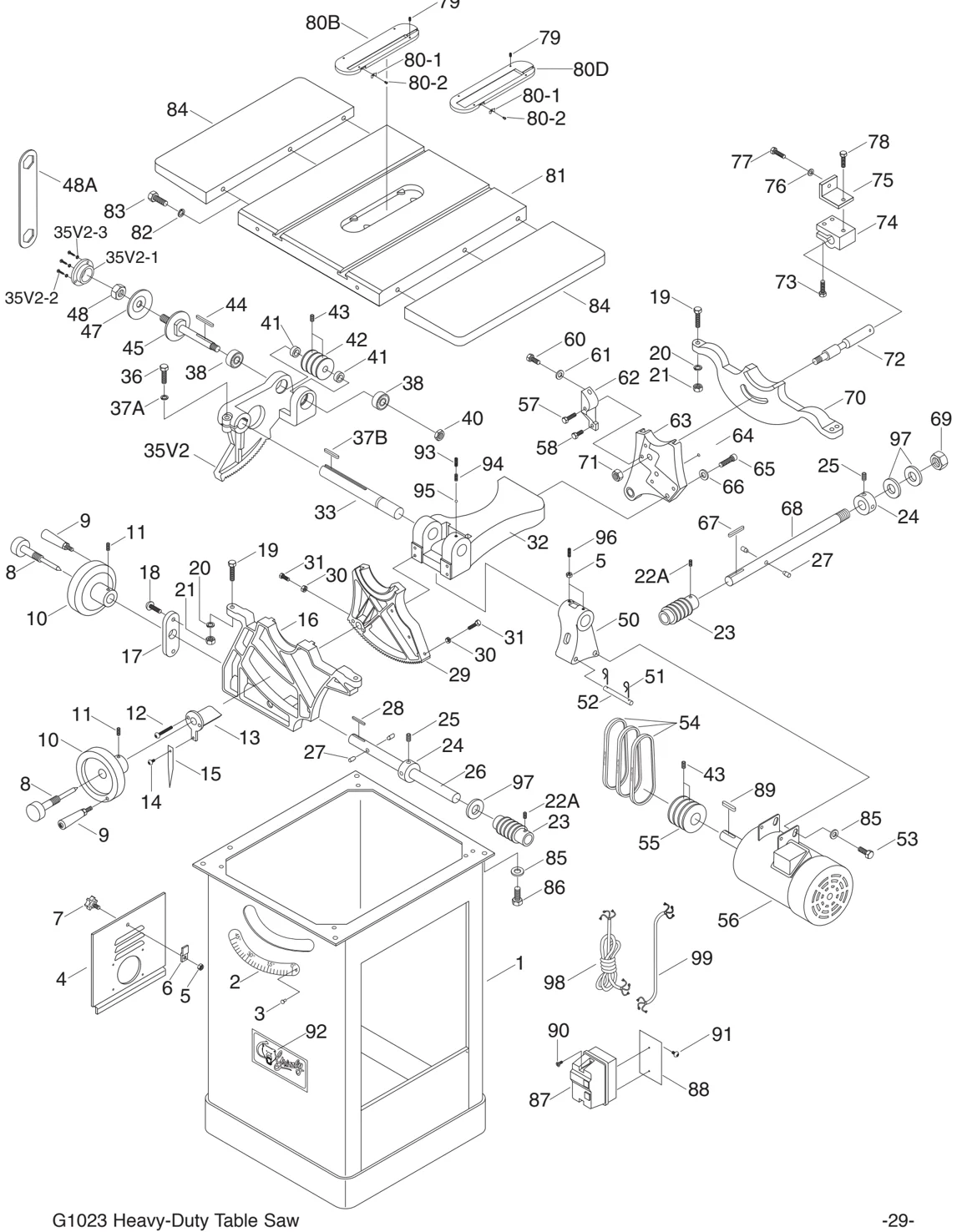
| REF | PART # | DESCRIPTION |
|---|---|---|
| 1 | P1023001 | CABINET |
| 2 | P1023002 | SCALE |
| 3 | P1023003 | TAP SCREW #6 X 1/2 |
| 4 | P1023004 | TRAP DOOR |
| 5 | P1023005 | HEX NUT 5/16-18 |
| 6 | P1023006 | LATCH |
| 7 | P1023007 | KNOB |
| 8 | P1023008 | HANDWHEEL LOCK V1.12.95 |
| 9 | P1023009 | HANDLE V1.12.95 |
| 10 | P1023010 | HANDWHEEL V2.01.06 |
| 11 | P1023011 | SET SCREW 1/4-20 X 5/16 |
| 12 | P1023012 | PHLP HD SCR 10-24 X 2 |
| 13 | P1023013 | POINTER BRACKET |
| 14 | P1023014 | PHLP HD SCR 5/16-18 X 3/8 |
| 15 | P1023015 | POINTER |
| 16 | P1023016 | FRONT TRUNNION |
| 17 | P1023017 | PLATE |
| 18 | P1023018 | PHLP HD SCR 5/16-18 X 1 |
| 19 | P1023019 | HEX BOLT 3/8-16 X 1-1/2 |
| 20 | P1023020 | LOCK WASHER 3/8 |
| 21 | P1023021 | HEX NUT 3/8-16 |
| 22A | P1023022A | SET SCREW 1/4-20 X 3/8 |
| 23 | P1023023 | WORM 1.410" OD |
| 24 | P1023024 | COLLAR |
| 25 | P1023025 | SET SCREW 5/16-18 X 1/4 |
| 26 | P1023026 | SHAFT V2.07.98 |
| 27 | P1023027 | DOWEL PIN |
| 28 | P1023028 | KEY 3/16 X 3/16 X 1-1/2 |
| 29 | P1023029 | GEARED TRUNNION V2.01.98 |
| 30 | P1023030 | HEX NUT 5/16-18 |
| 31 | P1023031 | HEX BOLT 5/16-18 X 1 |
| 32 | P1023032 | FLANGE |
| 33 | P1023033 | SHAFT |
| 35V2 | P1023035V2 | GEARED BEARING HOUSING V2 |
| 35V2-1 | P1023035V2-1 | PLATE |
| 35V2-2 | P1023035V2-2 | PHLP HD SCR 10-24 X 3/8 |
| 35V2-3 | P1023035V2-3 | LOCK WASHER #10 |
| 36 | P1023036 | HEX BOLT 3/8-16 X 1-1/2 |
| 37A | P1023037A | LOCK WASHER 3/8 |
| 37B | P1023037B | KEY 1/4 X 1/4 X 2 |
| 38 | P1023038 | BALL BEARING 6203-2RS |
| 39 | P1023039 | INT RETAINING RING 40MM |
| 40 | P1023040 | JAM NUT 5/8-18 |
| 41 | P1023041 | COLLAR |
| 42 | P1023042 | ARBOR PULLEY |
| 43 | P1023043 | SET SCREW 1/4-20 X 1/2 |
| 44 | P1023044 | KEY 5 X 5 X 45 |
| 45 | P1023045 | BLADE ARBOR W/SHAFT |
| 47 | P1023047 | ARBOR FLANGE |
| 48 | P1023048 | ARBOR NUT 5/8-12 LH |
| 48A | P1023048A | OPEN-END ARBOR WRENCH 7/8 X 7/8" |
| 49A | P1023049A | SET SCREW 5/16-18 X 1/2 |
| 50 | P1023050 | MOTOR FRAME SUPPORT V2.12.95 |
| REF | PART # | DESCRIPTION |
|---|---|---|
| 51 | P1023051 | CLIP |
| 52 | P1023052 | PIVOT PIN |
| 53 | P1023053 | HEX BOLT 7/16-20 X 3/4 |
| 54 | P1023054 | V-BELT 3L270 FM25 QTY 3 |
| 55 | P1023055 | MOTOR PULLEY |
| 56 | P1023056 | MOTOR 3 HP |
| 56A | P1023056A | MOTOR 3 HP 220V 1-PH V4.10.01 |
| 57 | P1023057 | HEX BOLT 5/16-18 X 2-1/4 |
| 58 | P1023058 | HEX BOLT 5/16-18 X 1 |
| 60 | P1023060 | HEX BOLT 5/16-18 X 3/4 |
| 61 | P1023061 | FLAT WASHER 5/16 |
| 62 | P1023062 | SUPPORT BRACKET |
| 63 | P1023063 | FLANGE CASTING V1.12.95 |
| 64 | P1023064 | ROLL PIN 5/16 X 5/8 |
| 65 | P1023065 | CAP SCREW 3/8-16 X 1 |
| 66 | P1023066 | FLAT WASHER 3/8 |
| 67 | P1023067 | KEY 3/16 X 3/16 X 1-9/16 |
| 68 | P1023068 | SHAFT |
| 69 | P1023069 | LOCK NUT 3/4-16 |
| 70 | P1023070 | REAR TRUNNION V3.02.96 |
| 71 | P1023071 | JAM NUT 5/8-18 |
| 72 | P1023072 | BLADE GUARD SUPPORT |
| 73 | P1023073 | HEX BOLT 5/16-18 X 1 |
| 74 | P1023074 | BLOCK |
| 75 | P1023075 | BLOCK ANGLE |
| 76 | P1023076 | FLAT WASHER 5/16 |
| 77 | P1023077 | HEX BOLT 5/16-18 X 3/4 |
| 78 | P1023078 | HEX BOLT 5/16-18 X 1 |
| 79 | P1023079 | SET SCREW 1/4-20 X 1/2 |
| 80-1 | P1023080-1 | SPRING CLIP 10 X 30.7 X 7.5 |
| 80-2 | P1023080-2 | PHLP HD SCR 10-24 X 3/8 |
| 80B | P1023080B | STD TABLE INSERT 8.5 |
| 80D | P1023080D | DADO INSERT |
| 81 | P1023081 | TABLE |
| 82 | P1023082 | LOCK WASHER 7/16 |
| 83 | P1023083 | HEX BOLT 3/8-16 X 1-1/4 |
| 84 | P1023084 | EXT. WING |
| 85 | P1023085 | FLAT WASHER 7/16 |
| 86 | P1023086 | HEX BOLT 7/16-20 X 3/4 |
| 87 | P1023087 | MAGNETIC SWITCH 3HP 1PH |
| 88 | P1023088 | SWITCH MOUNT BRACKET |
| 89 | P1023089 | KEY 5 X 5 X 40 |
| 90 | P1023090 | WHITE SWITCH COVER SCREW V1.12.95 |
| 91 | P1023091 | PHLP HD SCR 1/4-20 X 3/8 |
| 92 | P1023092 | LABEL |
| 93 | P1023093 | SET SCREW 5/16-18 X 3/8 |
| 94 | P1023094 | SPRING 5.5 X 12 X 7 |
| 95 | P1023095 | BALL |
| 96 | P1023096 | SET SCREW 5/16-18 X 1-1/4 |
| 97 | P1023097 | WAVE WASHER |
| 98 | P1023098 | POWER CORD 12G X 3W 86"L |
| 99 | P1023099 | POWER CORD 12G X 3W 36"L |
-30- G1023 Heavy-Duty Table Saw
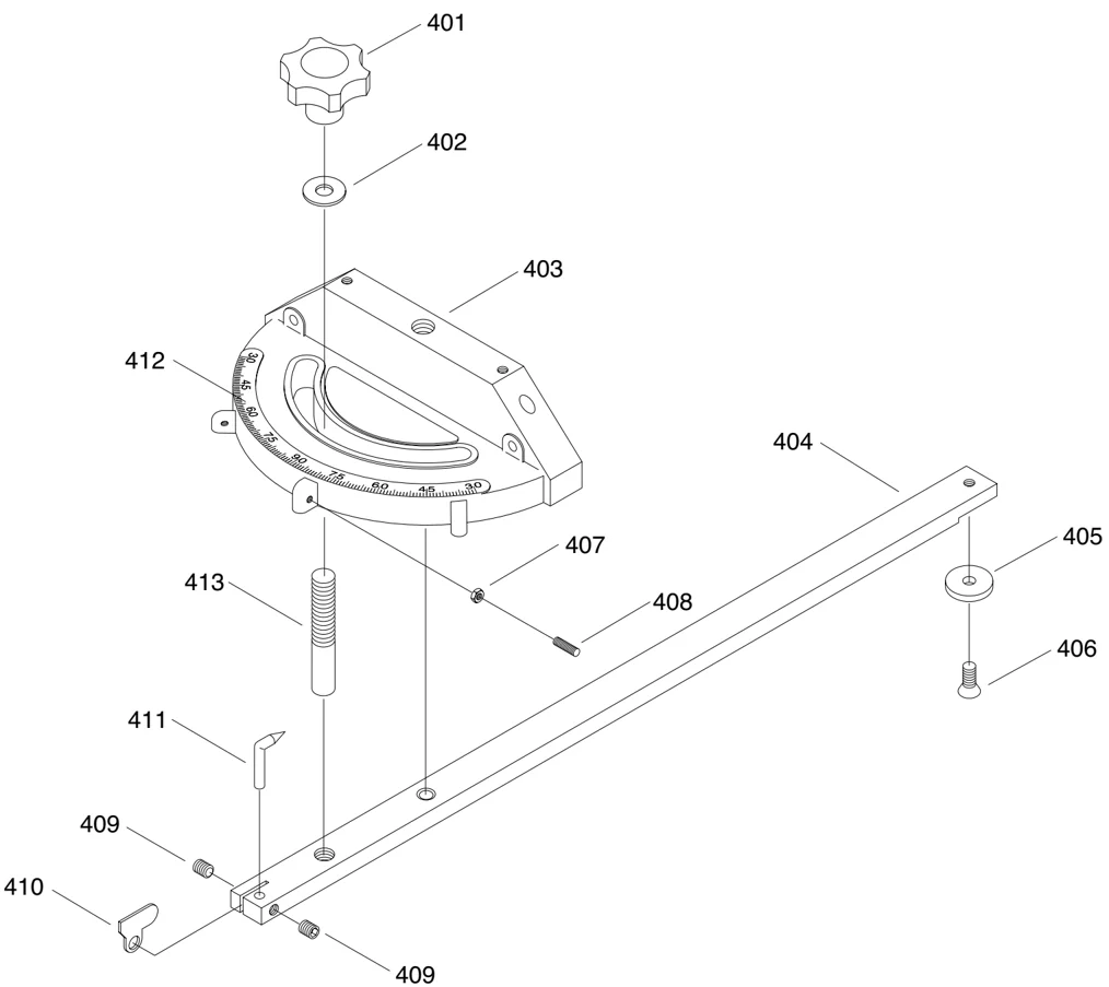
| REF | PART # | DESCRIPTION |
|---|---|---|
| 401 | P1023401 | KNOB |
| 402 | P1023402 | FLAT WASHER 1/4 |
| 403 | P1023403 | MITER GAUGE BODY V2.05.07 |
| 404 | P1023404 | ADJUSTABLE MITER BAR |
| 405 | P1023405 | T-SLOT WASHER 3MM |
| 406 | P1023406 | FLAT HD SCR 1/4-20 X 5/16 |
| 407 | P1023407 | HEX NUT 10-24 |
| REF | PART # | DESCRIPTION |
|---|---|---|
| 408 | P1023408 | SET SCREW 10-24 X 5/8 |
| 409 | P1023409 | SET SCREW 10-24 X 1/4 |
| 410 | P1023410 | MITER GAUGE STOP |
| 411 | P1023411 | POINTER |
| 412 | P1023412 | MITER GAUGE SCALE |
| 413 | P1023413 | STUD |
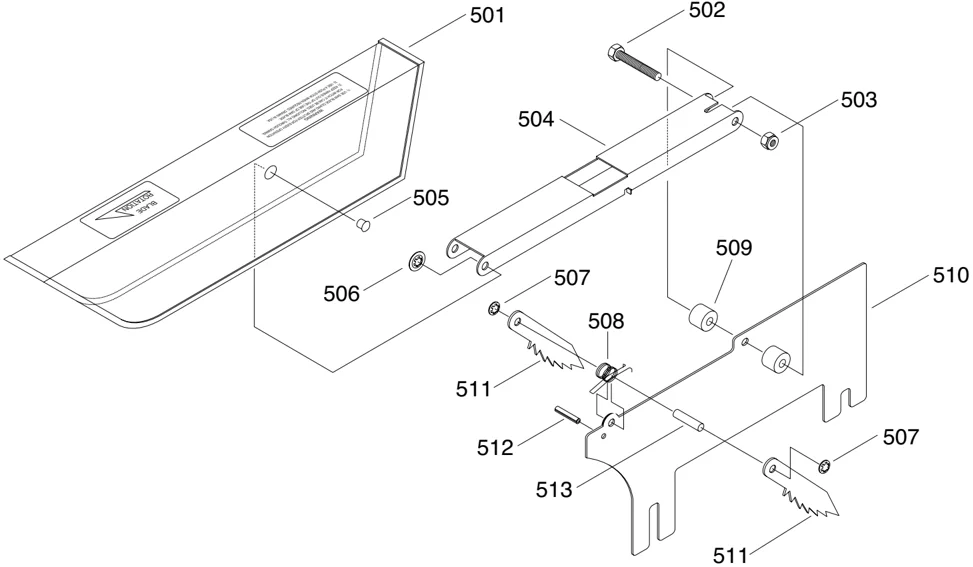
| REF | PART # | DESCRIPTION |
|---|---|---|
| 501 | P1023501 | BLADE GUARD |
| 502 | P1023502 | HEX BOLT M6-1 X 40 |
| 503 | P1023503 | LOCK NUT M6-1 |
| 504 | P1023504 | SUPPORTING ARM |
| 505 | P1023505 | PIVOT PIN |
| 506 | P1023506 | ROLL PIN 4 X 24 |
| 507 | P1023507 | RETAINER |
| REF | PART # | DESCRIPTION |
|---|---|---|
| 508 | P1023508 | SPRING 14 X 6 |
| 509 | P1023509 | SPACER |
| 510 | P1023510 | COMPLETE BLADE GUARD ASSY |
| 511 | P1023511 | PAWL |
| 512 | P1023512 | ROLL PIN 4 X 22 |
| 513 | P1023513 | FLAT HD SCR M5-.8 X 12 |
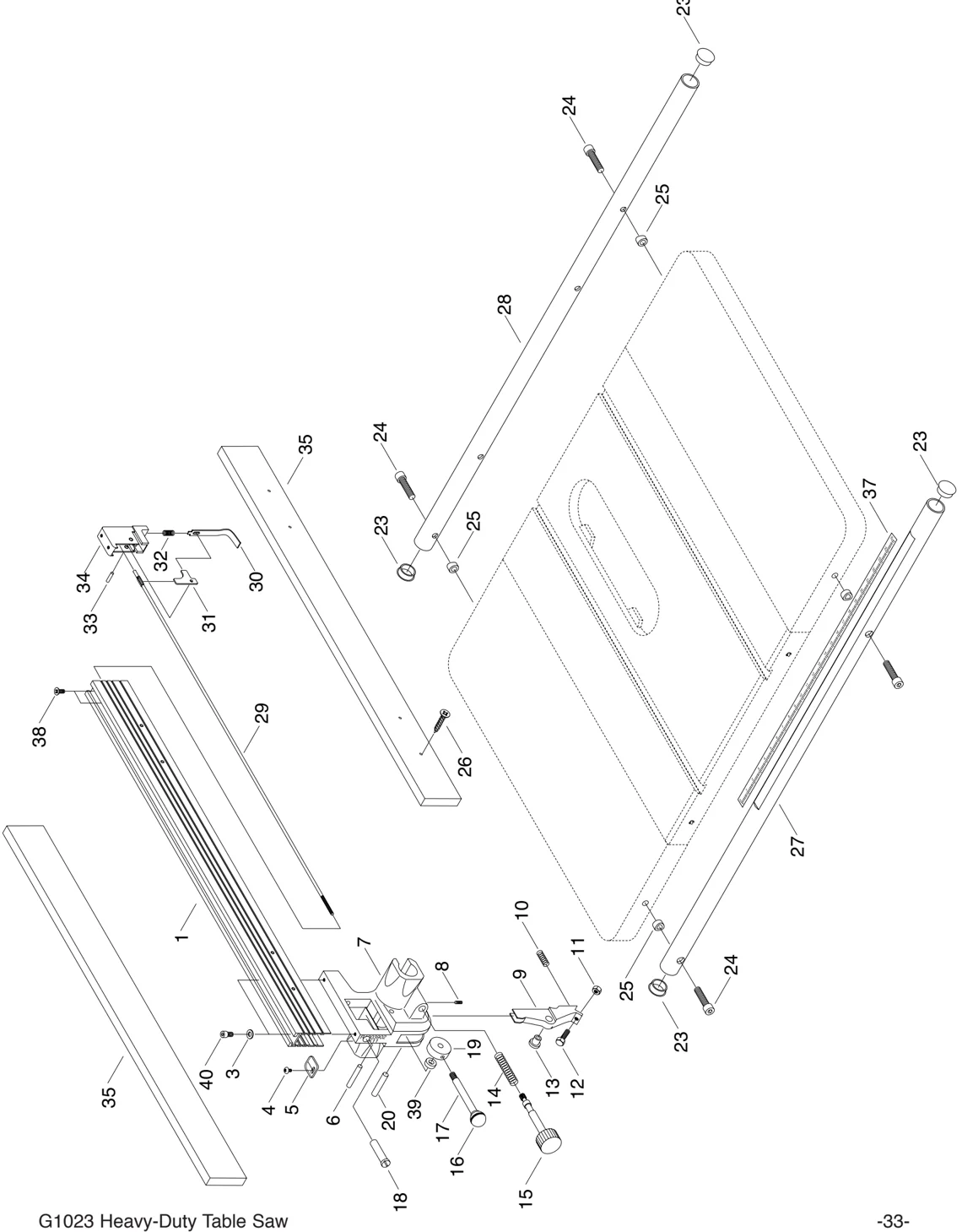
| REF | PART # | DESCRIPTION |
|---|---|---|
| 601 | P1023601 | FENCE |
| 602 | P1023602 | FLAT HD SCR M8-1.25 X 12 |
| 603 | P1023603 | FLAT WASHER 8MM |
| 604 | P1023604 | PHLP HD SCR M5-.8 X 8 |
| 605 | P1023605 | WIDTH POINTER |
| 606 | P1023606 | SHAFT FOR CLAMP |
| 607 | P1023607 | FRONT CLAMP |
| 608 | P1023608 | SET SCREW 1/4-20 X 3/8 |
| 609 | P1023609 | CLAMP SHOE |
| 610 | P1023610 | SPRING 11 X 40 X 8 |
| 611 | P1023611 | HEX NUT 5/16-18 |
| 612 | P1023612 | HEX BOLT 5/16-18 X 1 |
| 613 | P1023613 | SHAFT BUSHING |
| 614 | P1023614 | SPRING 16 X 65 X 9 |
| 615 | P1023615 | PINION W/KNOB |
| 616 | P1023616 | KNOB |
| 617 | P1023617 | LOCK LEVER |
| 618 | P1023618 | FENCE ADJUSTER |
| 619 | P1023619 | ECCENTRIC |
| REF | PART # | DESCRIPTION |
|---|---|---|
| 620 | P1023620 | SHAFT FOR ECCENTRIC |
| 623 | P1023623 | PLUG |
| 624 | P1023624 | CAP SCREW 3/8-16 X 1-1/2 |
| 625 | P1023625 | FENCE RAIL SPACER |
| 626 | P1023626 | RETAINER |
| 627 | P1023627 | FRONT RAIL |
| 628 | P1023628 | REAR RAIL |
| 629 | P1023629 | LOCK LINK |
| 630 | P1023630 | CLAMP HOOK |
| 631 | P1023631 | LEVER |
| 632 | P1023632 | SPRING 10 X 25 X 8 |
| 633 | P1023633 | PIN 6.35 X 20 |
| 634 | P1023634 | BLOCK |
| 635 | P1023635 | FACE BOARD 2 13/16" X 33 5/16" |
| 636 | P1023636 | FORMICA FACE 2 13/16" X 33 5/16" |
| 637 | P1023637 | SELF-STICK MEASURING TAPE |
| 638 | P1023638 | FLAT HD SCR M8-1.25 X 12 |
| 639 | P1023639 | SPACER |
| 640 | P1023640 | CAP SCREW 5/16-18 X 1/2 |
MACHINE DATA
GRIZZLY MODEL G1023 TABLE SAW
- Design Type ........ 10" Tilting Arbor
- Maximum Diameter of Saw Blade ........ 10"
- Diameter of Arbor ........ 5/8"
Capacities:
- Maximum Depth of Cut at 90° ........ 3 1/8"
- Maximum Depth of Cut at 45° ........ 2 1/8"
- Maximum Rip to Right of Blade (Standard) ........ 26"
- Maximum Rip to Right of Blade (Optional) ........ 46"
- Maximum Rip to Left of Blade ........ 11"
- Distance Front of Table to Center of Blade ........ 17"
- Table in Front of Blade at Maximum Cut ........ 12"
- Maximum Width of Dado ........ 13 1/16"
Overall Dimensions:
- With Wings and Guide Bars ........ 50" W x 31 5/16" D
- Weight (Shipping) ........ 425 lbs.
Construction:
- Table ........ Ground Cast Iron
- Stand ........ Pre-formed Steel
- Miter Gauge ........ Cast Iron/Steel Bar
- Trunnions ........ Cast Iron
Table:
- Height ........ 34"
- Size ........ 27 1/8" deep x 20 1/8" wide
- Size w/Extension Wings ........ 27 1/8" deep x 36 1/4" wide
- Miter Gauge Groove Type ........ T-slot
- Spindle Bearings ........ Shielded and Lubricated-For-Life/Ball
Motor:
-
Type ........ TEFC Capacitor Start Induction
-
Horsepower ........ 3 HP
-
Power Transfer ........ Triple Belt Drive
-
Phase / Cycle ........ Single Phase / 60 HZ
-
Voltage ........ 220V
-
Amps ........ 18 A
-
Motor RPM ........ 3450 RPM
-
Blade RPM ........ 4140 RPM
-
Bearings ........ Shielded and Lubricated-For-Life / Ball
-
Switch ........ Magnetic with Thermal Overload Protector
Specifications, while deemed accurate, are not guaranteed.
TROUBLE SHOOTING GUIDE
| SYMPTOM | POSSIBLE CAUSE | CORRECTIVE ACTION |
|---|---|---|
| Motor will not start. | 1. Low voltage.2. Open circuit in motor or loose connections. | 1. Check power line for proper voltage.2. Inspect all lead connections on motor for loose or open connections. |
| Motor will not start; fuses or circuit breakers blow. | 1. Short circuit in line cord or plug.2. Short circuit in motor or loose connections.3. Incorrect fuses or circuit breakers in power line. | 1. Inspect cord or plug for damaged insulation and shorted wires.2. Inspect all connections on motor for loose or shorted terminals or worn insulation.3. Install correct fuses or circuit breakers. |
| Motor overheats. | 1. Motor overloaded.2. Air circulation through the motor restricted. | 1. Reduce load on motor.2. Clean out motor to provide normal air circulation. |
| Motor stalls (resulting in blown fuses or tripped circuit). | 1. Short circuit in motor or loose connections.2. Low voltage.3. Incorrect fuses or circuit breakers in power line.4. Motor overloaded. | 1. Inspect connections on motor for loose or shorted terminals or worn insulation.2. Correct the low voltage conditions.3. Install correct fuses or circuit breakers.4. Reduce load on motor. |
| Machine slows when operating. | Applying too much pressure to workpiece. | Feed workpiece slower. |
| Loud, repetitious noise coming from machine. | 1. Pulley setscrews or keys are missing or loose.2. Motor fan is hitting the cover.3. V-belts are defective | 1. Inspect keys and setscrews. Replace or tighten if necessary.2. Tighten fan or shim cover.3. Replace V-belts. See Maintenance. |
| Blade is not square w/mitter slot or fence is not square to blade. | 1. Blade is warped.2. Table top is not parallel to blade.3. Fence is not parallel to blade. | 1. Replace blade.2. Make table parallel to blade. See Adjustments.3. Make fence parallel to blade. See Adjustments. |
| Fence hits table top when sliding on to the table. | 1. Front rail is bolted too low on the table.2. Rear rail is bolted too low on the table. | 1. Raise front rail.2. Raise rear rail. |
| Blade does not reach 90°. | 1. 90° stop bolt is out of adjustment.2. Pointer bracket is hitting before the blade reaches 90°. | 1. Adjust 90° stop bolt. See Adjustments.2. File down the right side of the pointer bracket until the blade can reach 90°. |
| Blade hits insert at 45°. | 1. Hole in insert is inadequate.2. Table out of alignment.3. Blade position is incorrect. | 1. File or mill the hole in the insert.2. Align table. See Adjustments.3. Adjust blade position. See Adjustments. |
| Blade won’t go beneath table surface. | Table top too low. | Raise table top w/washers. |
| Hand wheels won’t turn. | 1. Hand wheel key is inserted too far.2. Bullets are wedged.3. Roll pin or setscrew in worm gear is contacting geared trunnion. | 1. Remove hand wheel and adjust key.2. Remove hand wheel and adjust bullets. |
Grizzly WARRANTY CARD
Name_______________________________________________________________ Street_______________________________________________________________ City _______________________________ State__________________________ Zip ______________________ Phone #_____________________________ Email _______________________ Model #_____________________________ Order #______________________ Serial #__________________
The following information is given on a voluntary basis. It will be used for marketing purposes to help us develop better products and services. Of course, all information is strictly confidential.
1. How did you learn about us? ____ Advertisement ____ Friend ____ Catalog ____ Card Deck ____ Website ____ Other:
2. Which of the following magazines do you subscribe to? ____ Cabinetmaker & FDM ____ Popular Science ____ Wooden Boat ____ Family Handyman ____ Popular Woodworking ____ Woodshop News ____ Hand Loader ____ Precision Shooter ____ Woodsmith ____ Handy ____ Projects in Metal ____ Woodwork ____ Home Shop Machinist ____ RC Modeler ____ Woodworker West ____ Journal of Light Cont. ____ Rifle ____ Woodworker’s Journal ____ Live Steam ____ Shop Notes ____ Other: ____ Model Airplane News ____ Shotgun News ____ Old House Journal ____ Today’s Homeowner ____ Popular Mechanics ____ Wood
3. What is your annual household income? ____ $20,000-$29,000 ____ $30,000-$39,000 ____ $40,000-$49,000 ____ $50,000-$59,000 ____ $60,000-$69,000 ____ $70,000+
4. What is your age group? ____ 20-29 ____ 30-39 ____ 40-49 ____ 50-59 ____ 60-69 ____ 70+
5. How long have you been a woodworker/metalworker? ____ 0-2 Years ____ 2-8 Years ____ 8-20 Years ____ 20+ Years
6. How many of your machines or tools are Grizzly? ____ 0-2 ____ 3-5 ____ 6-9 ____ 10+
7. Do you think your machine represents a good value? ____ Yes ____ No
8. Would you recommend Grizzly Industrial to a friend? ____ Yes ____ No
9. Would you allow us to use your name as a reference for Grizzly customers in your area? Note: We never use names more than 3 times. ____ Yes ____ No
10. Comments: ___________________________________________________________________ _______________________________________________________________________________ _______________________________________________________________________________ _______________________________________________________________________________ _______________________________________________________________________________
CUT ALONG DOTTED LINE

FOLD ALONG DOTTED LINE
Place Stamp Here
Grizzly Industrial, Inc.®
GRIZZLY INDUSTRIAL, INC. P.O. BOX 2069 BELLINGHAM, WA 98227-2069
FOLD ALONG DOTTED LINE
Send a Grizzly Catalog to a friend:
Name________________________________________ Street______________________________________ City________________________State________Zip________
TAPE ALONG EDGES--PLEASE DO NOT STAPLE

WARRANTY & RETURNS
Grizzly Industrial, Inc. warrants every product it sells for a period of 1 year to the original purchaser from the date of purchase. This warranty does not apply to defects due directly or indirectly to misuse, abuse, negligence, accidents, repairs or alterations or lack of maintenance. This is Grizzly’s sole written warranty and any and all warranties that may be implied by law, including any merchantability or fitness, for any particular purpose, are hereby limited to the duration of this written warranty. We do not warrant or represent that the merchandise complies with the provisions of any law or acts unless the manufacturer so warrants. In no event shall Grizzly’s liability under this warranty exceed the purchase price paid for the product and any legal actions brought against Grizzly shall be tried in the State of Washington, County of Whatcom.
We shall in no event be liable for death, injuries to persons or property or for incidental, contingent, special, or consequential damages arising from the use of our products.
To take advantage of this warranty, contact us by mail or phone and give us all the details. We will then issue you a “Return Number,” which must be clearly posted on the outside as well as the inside of the carton. We will not accept any item back without this number. Proof of purchase must accompany the merchandise.
The manufacturers reserve the right to change specifications at any time because they constantly strive to achieve better quality equipment. We make every effort to ensure that our products meet high quality and durability standards and we hope you never need to use this warranty.
Please feel free to write or call us if you have any questions about the machine or the manual.
Thank you again for your business and continued support. We hope to serve you again soon.
grizzly.com
TOOL WEBSITE
Buy Direct and Save with Grizzly® – Trusted, Proven and a Great Value!
Since 1983
Visit Our Website Today For Current Specials!
ORDER
24 HOURS A DAY!
1-800-523-4777
VISA MasterCard DISCOVER NOVUS AMERICAN EXPRESS