Grizzly IMPORTS, INC.
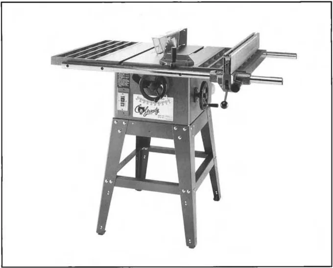
10" TABLE SAW
MODEL G1022 AND G1022Z
INSTRUCTION MANUAL

COPYRIGHT © 1986 BY GRIZZLY IMPORTS, INC. REG.# TX 3 170 572
WARNING: NO PORTION OF THIS MANUAL MAY BE REPRODUCED IN ANY SHAPE
OR FORM WITHOUT THE WRITTEN APPROVAL OF GRIZZLY IMPORTS, INC.
REVISED MAY, 1997. PRINTED IN TAIWAN
WARRANTY CARD
NAME ________________________________ PHONE NUMBER ________________________________
STREET ________________________________
CITY ________________________________ STATE __________ ZIP __________
MODEL # ________________________________ PURCHASED FROM GRIZZLY, BELLINGHAM, WA □ OR WILLIAMSPORT, PA □
INVOICE # ________________________________
The following information is given on a voluntary basis. This information will be used for marketing purposes to help Grizzly develop better products. Your name will be included in our mailing list only. It will not be sold to other companies. Of course, all information is strictly confidential.
- How did you find out about us?
___ Advertisement ___ Friend ___ Other ________________________________ ___ Catalog ___ Card deck
-
Do you think your machine represents good value? YES ___ NO ___
-
Would you allow us to use your name as a reference for Grizzly customers in your area? YES ___ NO ___ (Note: Your name will be used a maximum of three times.)
-
To which of the following publications do you subscribe? Check all that apply.
___ Fine Woodworking ___ Popular Woodworking ___ FDM ___ Practical Homeowner ___ American Woodworker ___ Fine Homebuilding ___ Wood & Wood Products ___ Home Handyman ___ Woodwork ___ Workbench ___ Old House Journal ___ Shop Notes ___ WOOD ___ Woodsmith ___ Journal of Light Construction ___ Cabinetmaker ___ Woodworker's Journal ___ Woodshop News ___ Wooden Boat ___ Other ________________________________
- What is your annual household income?
___ $20,000-$30,000 ___ $60,001-$70,000 ___ $30,001-$40,000 ___ $70,001-$80,000 ___ $40,001-$50,000 ___ $80,001-$90,000 ___ $50,001-$60,000 ___ + $90,000
- To which age group do you belong?
___ 20-30 ___ 41-50 ___ 61-70 ___ 31-40 ___ 51-60 ___ +70
- Which of the following stationary woodworking machines do you own? Check all that apply.
___ Table Saw ___ Jointer ___ Lathe ___ Scroll Saw ___ Band Saw ___ Planer ___ Panel Saw ___ Mortiser ___ Radial Arm Saw ___ Drill Press ___ Air Compressor & tools ___ Other ________________________________ ___ Wide Belt Sander ___ Shaper ___ Dust Collector ___ Drum Sander ___ Power Feeder ___ Vacuum/Veneer Press
-
How many of the machines you checked in Question 7 are Grizzly machines? ________________________________
-
Which of the following portable woodworking machines or power tools do you own? Check all that apply.
___ Circular Saw ___ Saber Saw ___ Miter Saw ___ Biscuit Joiner Other: ________________________________ ___ Drill/Driver ___ Recipro Saw ___ Belt Sander ___ Orbital Sander ___ R-O Sander ___ Router ___ Planer ___ Detail Sander
- Which of these machines or other tools would you like Grizzly to carry? Check all that apply.
___ Radial Arm Saw ___ Biscuit Joiner ___ Combination Planer/Joiner Other: ________________________________ ___ Panel Saw ___ Pin Router ___ 12" Table Saw ___ Vertical Spindle Sander ___ Mortiser ___ 24" Planer
- Of all the mail order woodworking companies you have purchased from, how do you rate Grizzly in terms of overall customer satisfaction?
___ The best ___ Above average ___ Average ___ Below average ___ The worst
- Comments: _________________________________________________________________________________________
FOLD ALONG THIS LINE
From:

GRIZZLY IMPORTS
P O BOX 2069
BELLINGHAM WA 98227-2069
PLACE STAMP HERE
FOLD ALONG THIS LINE
TAPE ALONG EDGES—PLEASE DO NOT STAPLE
Table Of Contents
| SECTION | TOPIC | PAGE |
|---|---|---|
| 1. | SAFETY | 2 |
| SAFETY RULES FOR ALL TOOLS | 2 | |
| ADDITIONAL SAFETY INSTRUCTIONS FOR TABLE SAWS | 3 | |
| 2. | CIRCUIT REQUIREMENTS | 4 |
| 110V OPERATION | 4 | |
| 220V OPERATION | 4 | |
| GROUNDING | 5 | |
| 3. | GENERAL INFORMATION | 6 |
| CLEAN UP | 7 | |
| SITE CONSIDERATIONS | 7 | |
| UNPACKING | 8 | |
| PIECE INVENTORY | 8-9 | |
| 4. | ASSEMBLY | 10 |
| STAND | 10-11 | |
| HAND WHEELS | 12 | |
| MOTOR | 12-15 | |
| WIRING | 15 | |
| EXTENSION WINGS | 16 | |
| FENCE RAILS | 17 | |
| FENCE | 17 | |
| BLADE | 18 | |
| BLADE GUARD | 18-19 | |
| 5. | ADJUSTMENTS | 20 |
| G1022 FENCE | 20-21 | |
| G1022Z FENCE | 22-23 | |
| TABLE INSERTS | 24 | |
| BLADE PARALLELISM | 25 | |
| 45° & 90° POSITIVE STOPS | 26 | |
| WORM GEAR | 27 | |
| MITER GAUGE | 27 | |
| 6. | OPERATIONS | 28 |
| TEST RUN | 28 | |
| BLADE SELECTION | 28-29 | |
| RIPPING | 30 | |
| CROSSCUTTING | 30 | |
| 7. | MAINTENANCE | 31 |
| GENERAL | 31 | |
| LUBRICATION | 31 | |
| TABLE | 31 | |
| V-BELT | 31 | |
| 8. | CLOSURE | 32 |
| G1022 PART BREAKDOWNS AND PARTS LIST | 33-37 | |
| G1022Z PART BREAKDOWNS AND PARTS LIST | 38-42 | |
| G1022 MACHINE DATA | 43 | |
| G1022Z MACHINE DATA | 44 | |
| TROUBLESHOOTING GUIDE | 45 | |
| WARRANTY AND RETURNS | 46 | |
| PUSH-STICK | 47 |
SECTION 1: SAFETY
WARNING: For Your Own Safety Read Instruction Manual Before Operating Saw
- Wear eye protection.
- Use saw-blade guard and spreader for every operation for which it can be used, including all through sawing.
- Keep hands out of the line of saw blade.
- Use a push-stick when required.
- Pay particular attention to instructions on reducing risk of kickback.
- Do not perform any operation freehand.
- Never reach around or over saw blade.
Safety Instructions For Power Tools
These safety rules cannot cover every situation in a woodshop. Consider your conditions when setting up or operating your table saw.
- KEEP GUARDS IN PLACE and in working order.
- REMOVE ADJUSTING KEYS AND WRENCHES. Form habit of checking to see that keys and adjusting wrenches are removed from tool before turning on.
- KEEP WORK AREA CLEAN. Cluttered areas and benches invite accidents.
- DON’T USE IN DANGEROUS ENVIRONMENT. Don’t use power tools in damp or wet locations, or expose them to rain. Keep work area well lit.
- KEEP CHILDREN AWAY. All visitors should be kept a safe distance from work area.
- MAKE WORK SHOP KID PROOF with padlocks, master switches, or by removing starter keys.
- DON’T FORCE TOOL. It will do the job better and safer at the rate for which it was designed.
- USE RIGHT TOOL. Don’t force tool or attachment to do a job for which it was not designed.
- USE PROPER EXTENSION CORD. Make sure your extension cord is in good condition. When using an extension cord, be sure it is rated Hard Service (grade S) or better. Conductor size must be 16 A.W.G. for cords up to 100 feet in length. An undersized cord will cause a drop in line voltage resulting in loss of power and overheating. Your extension cord must also contain a ground wire and plug pin. Always repair or replace extension cords if they become damaged. Minimum Gage for extension cord:
| 16 A.W.G. | 50ft |
|---|---|
| 16 A.W.G. | 100ft |
| 14 A.W.G. | 200ft |
| 12 A.W.G. | 300ft |
- WEAR PROPER APPAREL Do not wear loose clothing, gloves, neckties, rings, bracelets, or other jewelry which may get caught in moving parts. Non-slip footwear is recommended. Wear protective hair covering to contain long hair.
- ALWAYS USE SAFETY GLASSES. Also use face or dust mask if cutting operation is dusty. Everyday eyeglasses only have impact resistant lenses, they are NOT safety glasses.
-
SECURE WORK. Use clamps or a vise to hold work when practical. It's safer than using your hand and frees both hands to operate tool.
-
DON'T OVERREACH. Keep proper footing and balance at all times.
-
MAINTAIN TOOLS WITH CARE. Keep tools sharp and clean for best and safest performance. Follow instructions for lubricating and changing accessories.
-
DISCONNECT TOOLS before servicing; when changing accessories, such as blades, bits, cutters, and the like.
-
REDUCE THE RISK OF UNINTENTIONAL STARTING. Make sure switch is in off position before plugging in.
-
USE RECOMMENDED ACCESSORIES. Consult the owner's manual for recommended accessories. The use of improper accessories may cause risk of injury to persons.
-
CHECK DAMAGED PARTS. Before further use of the tool, a guard or other part that is damaged should be carefully checked to determine that it will operate properly and perform its intended function - check for alignment of moving parts, binding of moving parts, breakage of parts, mounting, and any other conditions that may affect its operation. A guard or other part that is damaged should be properly repaired or replaced.
-
DIRECTION OF FEED. Feed work into a blade or cutter against the direction of rotation of the blade or cutter only.
-
NEVER LEAVE TOOL RUNNING UNATTENDED. TURN POWER OFF. Don't leave tool until it comes to a complete stop.
Additional Safety Instructions For Table Saws
-
ALWAYS use guard, splitter and anti-kickback fingers on all "thru-sawing" operations. Thru-sawing operations are those when the blade cuts completely through the workpiece as in ripping or cross cutting.
-
ALWAYS hold the work firmly against the miter gauge or fence.
-
ALWAYS use a push-stick for ripping narrow stock. Refer to ripping applications on Page 30 of this manual, and Page 47 where push-stick use is covered in detail.
-
NEVER perform any operation "free-hand" which means using only your hands to support or guide the workpiece. Always use either the fence or the miter gauge to position and guide the work.
-
NEVER stand or have any part of your body in line with the path of the saw blade.
-
NEVER reach behind or over the blade with either hand for any reason.
-
MOVE the rip fence out of the way when cross cutting.
-
NEVER use the fence as a cut-off gauge when cross cutting.
-
NEVER attempt to free a stalled saw blade without first turning the saw OFF.
-
PROVIDE adequate support to the rear and sides of the saw table for wide or long workpieces.
-
AVOID KICKBACKS (work thrown back toward you) by keeping blade sharp, keeping rip fence parallel to the saw blade, keeping splitter and antikick-back fingers and guard in place and operating, by not releasing work before it is pushed all the way past the saw blade, and by not ripping work that is twisted or warped or does not have a straight edge to guide along the fence.
-
AVOID awkward operations and hand positions where a sudden slip could cause your hand to move into the blade.
SECTION 2: CIRCUIT REQUIREMENTS
110V Operation
The motor supplied with the G1022 and G1022Z is a dual-voltage 110/120V or 220/240V motor. Under normal use, the motor draws approximately 17.2 amps @ 110V and 8.6 amps @ 220V. We recommend a 20 amp circuit breaker for 110V and a 15 amp breaker for 220V. This should be satisfactory for normal use, while providing enough protection against motor damage caused by power surges. Grizzly recommends that the circuit you use should be dedicated, (i.e., the G1022 or G1022Z should provide the only draw from that circuit). If frequent circuit failures occur when using the table saw, contact our service department or your local electrical contractor.
CAUTION: Be sure that your particular electrical configuration complies with local and state codes. The best way to ensure compliance is to check with your local municipality or licensed electrician.
220V Operation
The motor supplied with your tablesaw is a dual-voltage 110/220V motor. Under normal use, the motor draws approximately 9 amps @ 220V. We recommend a 15 amp breaker for 220V. This should be satisfactory for normal use, while providing enough protection against motor damage caused by power surges. Grizzly recommends that the circuit you use should be dedicated, (i.e., the G1022 or G1022Z should provide the only draw from that circuit). If frequent circuit failures occur when using the table saw, contact our service department or your local electrical contractor.
CAUTION: Be sure that your particular electrical configuration complies with local and state codes. The best way to ensure compliance is to check with your local municipality or licensed electrician.
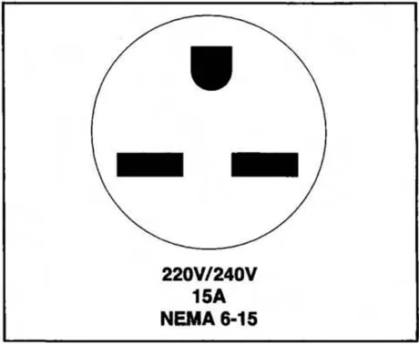
We recommend using the plug type illustrated in Figure 1 for 220V operation. Contact your local electrical contractor’s supply, a licensed electrician or our service department if you have questions about the configuration for your specific situation.

Grounding
CAUTION: THIS TOOL MUST BE GROUNDED WHILE IN USE TO PROTECT THE OPERATOR FROM ELECTRIC SHOCK.
In the event of a malfunction or breakdown, grounding provides a path of least resistance for electric current to reduce the risk of electric shock. This tool is equipped with an electric cord having an equipment-grounding conductor and a grounding plug. The plug must be plugged into a matching outlet that is properly installed and grounded in accordance with all local codes and ordinances.
Improper connections of the electrical-grounding conductor can result in risk of electric shock. The conductor with green or green and yellow striped insulation is the electrical-grounding conductor. If repair or replacement of the electric cord or plug is necessary, do not connect the equipment grounding conductor to a live terminal.
Under no circumstances should the grounding pin from any three-pronged plug be removed. If it will not fit the outlet, have the proper outlet installed by a qualified electrician.
Check with a qualified electrician or one of our service personnel if the grounding instructions are not completely understood, or if in doubt as to whether the tool is properly grounded. Use only 3-wire extension cords that have 3-prong grounding type plugs and 3-hole receptacles that accept the tool's plug. Figure 2.
Repair or replace damaged or worn cord immediately.
 Grounded Outlet Box—
Current
Carrying
Prongs
Grounding Blade Is—
Longest Of the Three Blades
-5- G1022 And G1022Z 10" Table Saw
SECTION 3: GENERAL INFORMATION
Grizzly Imports, Inc. is proud to offer the Model G1022 and G1022Z 10" Table Saw. This saw is a part of Grizzly's growing family of fine woodworking machinery. When used according to the guidelines stated in this manual, you can expect years of trouble-free, enjoyable operation.
The Model G1022/G1022Z is intended for home and medium-duty professional use. This saw features a 3,450 R.P.M., 1-1/2 H.P. capacitor-start motor, push-button ON/OFF switch, cast iron extension wings and a lever-lock rip fence.
All running parts utilize shielded ball bearings, which require no lubrication for the life of the bearings. Grizzly offers a number of helpful accessories for the Model G1022/G1022Z, including extended fence rails, additional 10" saw blades and a mobile base.
We are also pleased to provide this manual with the Model G1022/G1022Z. It was written to guide you through assembly, review safety considerations, and cover general operating procedures. It represents our latest effort to produce the best documentation possible. If you have any criticisms that you feel we should pay attention to in our next printing, please write to us at the Bellingham, WA address at the end of this section.
Most important, we stand behind our machines. We have an excellent Service Department at your disposal should the need arise. If you have any service questions or parts requests, please call or write to us at the location listed below.
Grizzly Imports, Inc. 2406 Reach Road Williamsport, PA 17701 Phone:(717) 326-3806 Fax:(800) 438-5901 E-Mail: Grizzlytec@aol.com Web Site: http://www.grizzlyimports.com
To comment on this manual write to:
Grizzly Imports, Inc. % Technical Documentation P.O. Box 2069 Bellingham, WA 98227
To operate this or any power tool safely and efficiently, it is essential to become as familiar with it as possible. The time you invest before you begin to use your Model G1022/G1022Z will be time well spent. DO NOT operate this machine until you are completely familiar with the contents of this manual.
Clean up
The table and other unpainted parts of the Model G1022/G1022Z are coated with a waxy oil that protects them from corrosion during shipment. Remove the protective coating with mineral spirits and paper towels. Do not use gasoline or other petroleum based solvents because of their extremely low flash points. Do not use chlorine-based solvents – if you happen to splash some onto a painted surface, you’ll ruin the finish.
WARNING!
Follow the safety rules listed below when working with solvents:
- Read and follow all directions and warnings on the solvent label.
- Work only in a well ventilated area.
- Do not work near any type of open flame (e.g., pilot lights, kerosene heaters, and so on).
- DO NOT smoke while working with flammable material.
- Paper towels from the cleaning process are extremely combustible. Dispose of waste towels so they do not create a fire hazard.
Site Considerations
- Floor Load: Your G1022/G1022Z Saw represents a large weight load in a small footprint. Most commercial floors are suitable for the table saw. Some residential floors may require additional build up to support both machine and operator.
- Working Clearances: Consider existing and anticipated needs, size of material to be processed through each machine, and space for auxiliary stands, work tables or other machinery when establishing a home for your table saw. Allow sufficient room to safely run your machines in any foreseeable operation.
- Lighting and Outlets: Lighting should be bright enough to eliminate shadow and prevent eye strain. Electrical circuits should be dedicated or large enough to handle amperage requirements. Outlets should be located near each machine so power or extension cords are clear of high-traffic areas. Observe local electrical codes for proper installation of new lighting, outlets, or circuits.
Unpacking
The Model G1022/G1022Z Table Saw is shipped from the manufacturer in a carefully packed carton. If you discover the machine is damaged after you've signed for delivery, please call Customer Service immediately for advice.
Save the containers and all packing materials for possible inspection by the carrier or its agent. Otherwise filing a freight claim can be difficult.
Caution: The G1022/G1022Z is a heavy machine (270 lbs. shipping weight). DO NOT over-exert yourself while unpacking or moving your machine – get assistance. In the event that your saw must be moved up or down a flight of stairs, be sure that the stairs are capable of supporting the combined weight of people and the machine.
When you are completely satisfied with the condition of your shipment, you should inventory its parts.
Piece Inventory
After all the parts have been removed from the carton, you should have:
- Stand Components
- Extension Wings (2)
- V-Belt
- Motor with Pulley
- Motor Bracket
- Motor Mount Plate
- Table Saw Unit
- Hand Wheels (2)
- Arbor Wrench
- Dado Insert
- Miter Gauge
- 10" General Purpose Saw Blade*
- Blade Guard
- Blade Guard Bracket
- Hardware Bags
- V-Belt Guard and Mounting Hardware
- V-Belt Guard Bracket
- Fence Unit
- Fence Rails (separate box)
-
- G1022Z only

Parts Overview
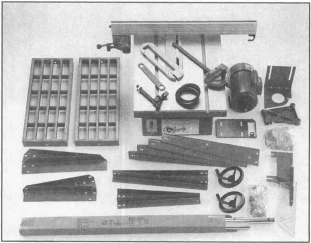
Guide Rail & Extension Wing Hardware Bag
| Qty | Description |
|---|---|
| 8 | Special Rail Bolts |
| 8 | Fence Rail Spacers |
| 4 | 10mm Flat Washer |
| 4 | M10 - 1.50 Hex Nuts |
| 6 | M10 - 1.50 x 25 Hex Bolts |
| 4 | 10mm x 4mm Thick Washers |
| 4 | Rubber Foot Pads |
Floor Stand Hardware Bag
| Qty | Description |
|---|---|
| 40 | 8mm - 1.25 x 16mm Carriage Bolts |
| 4 | 8mm - 1.25 x 19mm Hex Bolts |
| 52 | 8mm Flat Washers |
| 44 | 8mm - 1.25 Hex Nuts |
| 4 | M10 - 1.5 x 25mm Hex Bolts |
| 4 | M10 - 1.5 Hex Nuts |
| 4 | Plastic Feet |
Hand Wheel & Misc. Hardware Bag
| Qty | Description |
|---|---|
| 4 | Fence Rail Plugs |
| 2 | Hand Wheels |
| 1 | Fence Handle |
Plastic Belt Guard Hardware Bag
| Qty | Description |
|---|---|
| 4 | 1/4"- 20 x 2" Carriage Bolts |
| 1 | 1/4" Flat Washer |
| 1 | Sleeve |
| 1 | 1/4"-20 Wing Nut |
| 1 | Plastic Belt Guard |
Motor Mount Hardware Bag
| Qty | Description |
|---|---|
| 4 | 8mm - 1.25 x 25mm Hex Bolts |
| 8 | 8mm Flat Washers |
| 4 | 8mm - 1.25 Hex Nuts |
In the event that any non proprietary parts are missing (e.g. a nut or a washer), we would be glad to replace them, or, for the sake of expediency, replacements can be obtained at your local hardware store.

SECTION 4: ASSEMBLY
Stand Assembly
The G1022/G1022Z Table Saw is supplied with a heavy-duty stand. To assemble the stand:
- Fasten the plastic feet to all four legs using the M10 - 1.5 x 25mm Hex Bolts, 10mm Flat washers and M10 - 1.5 Hex Nuts supplied. Figure 3.
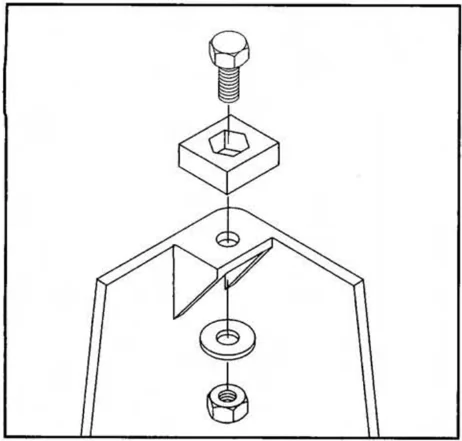
Figure 3.
- Locate the long upper and lower side braces (2 each) and bolt to the legs using the M8-1.25 x 16mm Carriage Bolts, 8mm Flat Washers and M8-1.25 Hex Nuts Supplied. Figure 4. Do not tighten any stand bolts until Step 6. Finger tighten only for now.
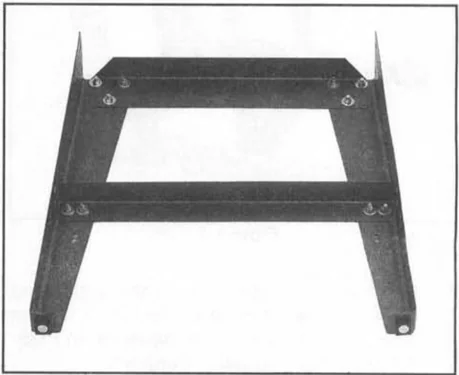
Figure 4. Assembled side panel.
- Attach the short upper and lower side braces to one of the assembled side panels. Use the M8 - 1.25 x 16mm Carriage Bolts, 8mm Flat Washers and M8-1.25 Hex Nuts supplied. Figure 5.
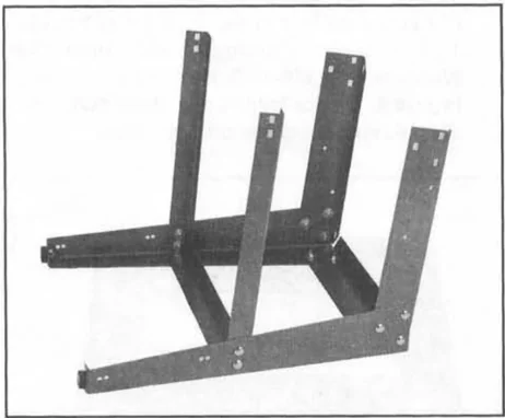
- Bolt the other side panel to the upper and lower braces using the M8-1.25 x 16mm Carriage Bolts, 8mm Flat Washers and M8-1.25 Hex Nuts supplied. Figure 6.
 Figure 6.
- Note the location of the mounting holes on the top of the stand. Turn the table saw body upside-down and place the stand (upside down) on the table saw, lining up the mounting holes at the four corners. Secure with four 8mm-1.25 x 19mm Hex Bolts, eight 8mm Flat Washers and four M8-1.25 Hex Nuts. Figure 7.
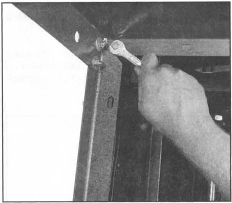
- Flip the entire table saw unit rightside-up and move it into its working position. Level the stand by checking all sides for symmetry. Measure diagonally from top to bottom and adjust the stand so both diagonals are equal. Tighten all of the stand bolts.
Handwheels
To mount the handwheels:
- Position a handwheel over the arbor raising shaft on the front of the saw. Be sure it fits completely over the shaft. The slots in the handwheel hole will engage with the roll pin on the shaft. Figure 8.
- Position the other handwheel similarly on the blade tilting shaft on the side of the saw.
- Screw the black plastic lock knobs onto the ends of the shafts to lock the handwheels in place.
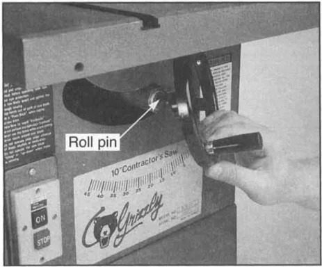
Roll pin 10" Contractor's Saw Grizzly Figure 8.
Motor
To mount the motor:
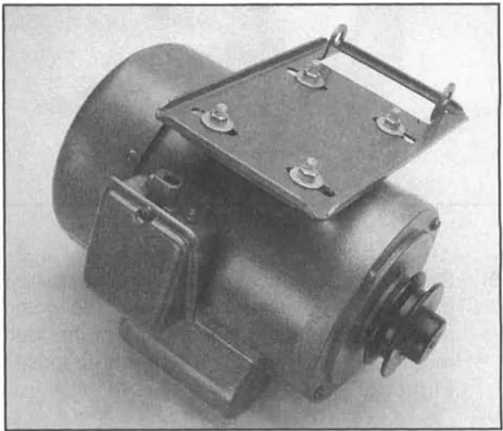
- Turn the motor upside down and attach the motor plate using the four 8mm-1.25 x 25mm hex bolts, 8mm washers and 8mm-1.25 hex nuts. Finger tighten only. Figure 9.
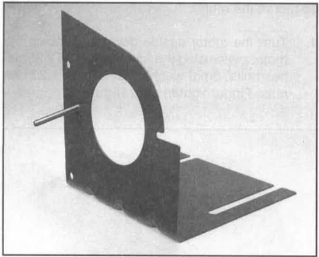
- Insert the 1/4"-20 x 2" hex bolt through the hole in the pulley guard bracket. Figure 10.
- Set the motor on end and slip the pulley guard bracket between the base of the motor and the motor plate. Tighten one of the four mounting bolts. Leave the other three loose. Figure 11.
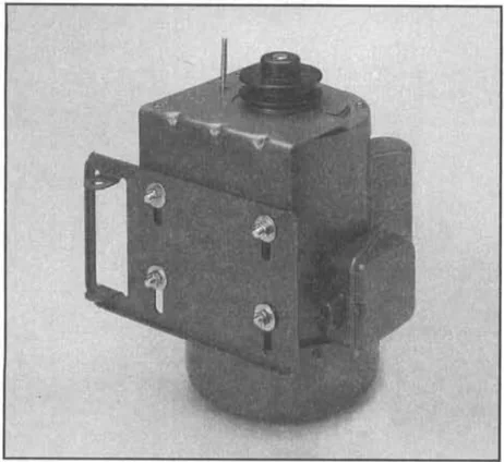
Figure 11.
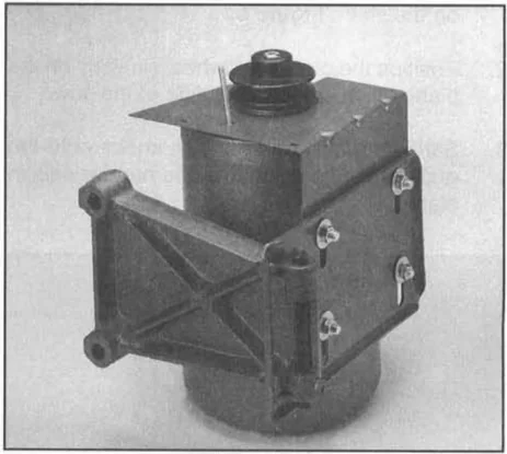
- Locate the motor mount bracket. Loosen the setscrew that holds the motor pivot rod in place and remove the rod. Line up the hole in the motor bracket with the hole in the motor plate and insert the motor pivot rod making sure the groove in the rod lines up with the setscrew in the mount bracket. Figure 12. Tighten the setscrew.
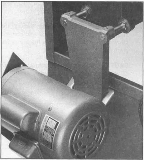
- Turn the arbor tilting handwheel until the arbor is set to 0°. Slide the motor assembly onto the linking bars through the holes in the motor bracket. Line up the setscrews with the grooves on the linking bars and tighten. Figure 13.
- Lift the motor up and slip the V-Belt over the grooves in the pulleys. Slowly let go of the motor allowing its weight to add tension to the V-Belt. Figure 14.
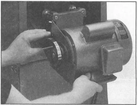
Figure 14.
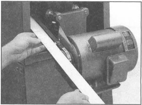
- Place a straightedge across the arbor pulley and the motor pulley. The straightedge should run across both pulleys evenly. Adjust the motor on its mount until pulleys are aligned, then tighten all the mounting bolts. Figure 15.
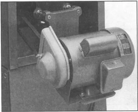
- Slip the pulley cover spacer over the pulley cover mounting bolt and fit the plastic pulley cover in place. Secure it with the wing nut provided. Figure 16.
Wiring
The switch, with attached power cord, is already mounted to the saw. To connect the wires from switch to motor:
-
Remove the motor junction box cover.
-
Feed the cord from the switch through the strain relief in the junction box and connect the wires for 110V or 220V per the wiring diagram enclosed. Figure 17.
CAUTION: If there is any confusion on how to wire the motor, or the wire diagram is missing, please call our customer service center for further instruction.
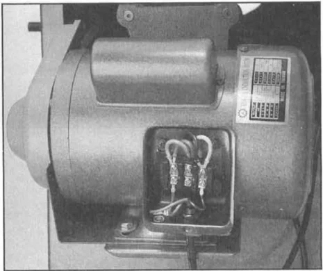
Figure 17.
-
Tighten the strain relief so the cord is attached securely to the motor junction box.
-
Secure the cover to the motor junction box.

Extension Wings
Inspect the extension wings for any burrs or foreign material that may inhibit assembly. The mating edges of the wings and table must be clean, smooth, and flat. Use a wire brush or file if necessary to clean up the edges. You will need a proven, steel straightedge. To install the extension wings:
- Attach each wing to the table using the six M10 - 1.50 x 25 hex bolts and 10mm x 4mm thick flat washers provided. Thread the center bolt in first, then the front and back bolts. Get the wings reasonably flush with the table. Do not completely tighten the bolts.
- Working front to back, align the front edge of the extension wing with the edge of the table so they are flush and tighten the front bolt.
- Raise or lower the rear of the extension wing until the middle of the wing is flush with the table top and tighten the middle bolt. Figure 18.
 Figure 18.
- Raise or lower the rear of the wing until the wing and table are flush. Tighten the bolt.
- Repeat Steps 2-4 for the other extension wing.
- Now, check the alignment of the table vs. both wings. Your straightedge should run flat across both wings and the table top. If the straightedge contacts both wings and the table evenly, you may skip to the next section. If it does not, continue to Step 7.
- If the wings tilt down, apply layers of masking tape under each bolt near the bottom edge of the wing.
- If the wing tilts up, apply layers of masking tape above each bolt near the top edge of the wing.
- Tighten bolts and adjust again as described in Steps 2-4.

Fence Rails
The rails should extend to the right of the saw and are attached to the table top with special bolts and dished spacers. The rails come packed in a separate box. To mount the rails:
- The two center bolts for each rail thread directly into the table top, the outer two bolts secure from the back side of the extension wing with hex nuts. Figure 19. Be sure that the rail with the built-in measuring rule is mounted on the front side of the machine, with the markings facing up.
- Insert the round, plastic plugs into the ends of each rail.
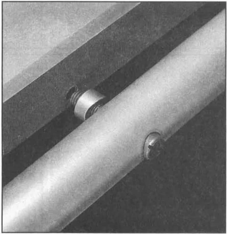
Figure 19.
Fence
To mount the fence:
- Thread the plastic knob onto the lock handle.
- Set the lock handle in the up position and slide the fence over the front and rear rails. Figure 20.
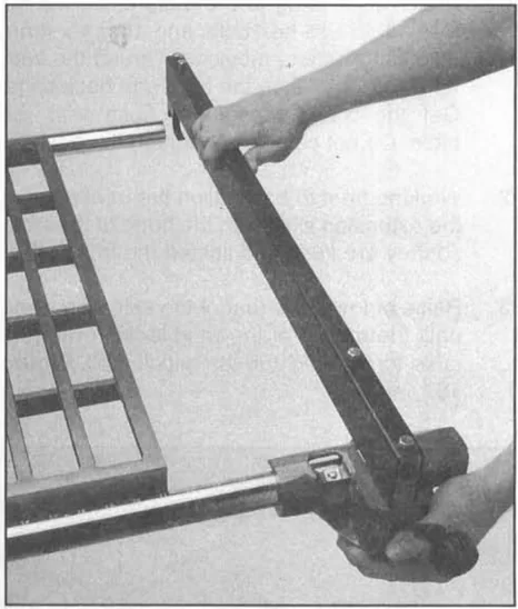
- The fence will require further adjustments covered in Adjustments Section.
Blade
The Model G1022 is not supplied with a blade. Please refer to our current catalog for a complete selection.
- Unthread the nut clockwise and remove the outside flange from the arbor. Note that there is a 3/4" diameter spacer on the arbor shaft, remove and discard it. Remember the arbor nut is a left-hand thread.
- Install the saw blade onto the arbor. Ensure that the blade teeth point toward you as you stand at the front of the saw. Slide on the flange and thread the arbor nut back on.
- Use the arbor wrench provided with the saw to tighten the arbor nut. Wedge a block of wood in the teeth of the blade to keep it from turning when tightening the nut. Figure 21.
- When removing the blade, use a block of wood to wedge the blade.
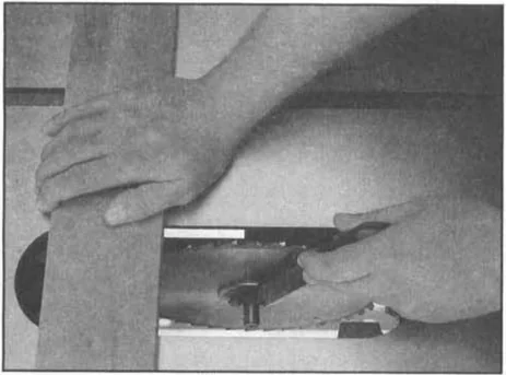
Figure 21.
Blade Guard
To mount the blade guard:
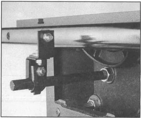
- Screw the threaded end of the support shaft into the hole in the back of the rear trunnion. The check nut on the shaft will be used to tighten the shaft in place. Leave it loose for now. Figure 22.
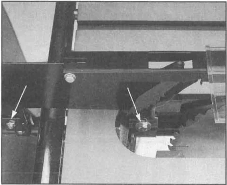
- Loosen the blade guard mounting bolt located just inside the table cut-out and guard mounting bolt on the end of the support shaft.

- Slip the slots at the bottom of the guard over the two mounting bolts. Figure 23. The washers should be between the bolt head and the slots. Rotate the support shaft to align the mounting bolts to the mounting slots on the guard.
-
Tighten the mounting bolts to secure the blade guard.
-
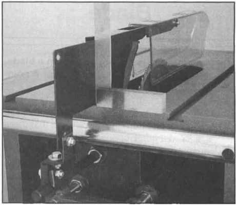
Using a machinist's or combination square, align the face of the splitter perpendicular to the surface of the saw table. Figure 24. a. Rotate the support shaft slightly. This will normally correct any minor misalignment. b. Add washers between the guard slots and the mounting bolts, if needed, to align the splitter to the saw blade. To verify alignment, run a straightedge along both sides of the blade, past the splitter.
- Tighten the check nut on the support shaft to hold it in place.
-19- G1022 And G1022Z 10" Table Saw

SECTION 5: ADJUSTMENTS
G1022 Fence
The fence must engage and square up on the front rail before the rear clamp engages the back rail. In essence, the rear clamp should act as a secondary mechanism for maintaining fence position. When adjusted correctly, the lever lock should only begin to apply pressure on the back rail over the last one third of its stroke. To adjust the fence:
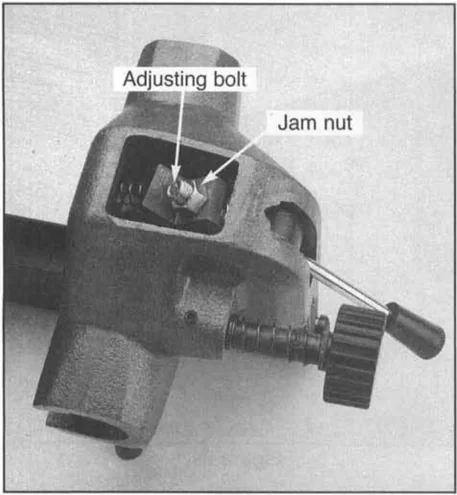
- First, make sure the front clamp is engaging the front rail with the lock handle at one half its throw. If the front clamp requires adjustment, loosen the check nut. Figure 25. Turn the adjusting bolt in if the front clamp is too far from the rail , out if it is too close.
Adjusting bolt Jam nut
Figure 25.
-
Now slide the fence along the rail until it is aligned with the edge of the miter slot. Lock the fence down.
-
Loosen the rear lock adjustment (the slotted screw on the front of the fence) until the rear locking lever ceases to engage the rear rail with the fence in the locked position. Figure 26.
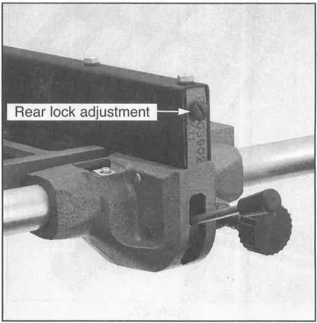
Rear lock adjustment
4. Loosen the adjustment bolts at the top of the fence. Figure 27. Move the straight portion of the fence until it is parallel with the miter slot from front to back. Re-tighten the bolts.
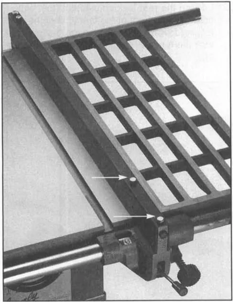
5. Loosen the locking lever until it is approximately two thirds engaged. Tighten the rear adjusting screw until the rear clamp just touches the back rail.
6. Loosen the locking lever and slide the fence along the rail. Return the fence to its position at the edge of the miter slot and slowly apply pressure to the lever. If adjustments are correct, the fence should square itself before the rear clamp engages. If the rear clamp engages before the fence is squared, loosen the screw one quarter turn and re-test.
Tip – Attach a piece of 3/4" thick hardwood to the blade side of the fence. This will keep thin materials from wedging between the fence and table, and will also protect the fence from coming in contact with the blade when dadoing or ripping thin stock. Figure 28.
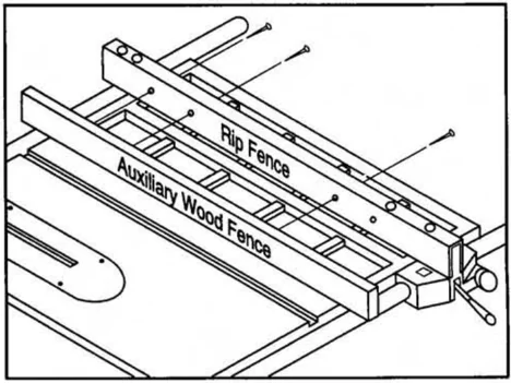
Figure 28.
7. Once the fence is adjusted, check the pointer and adjust if necessary. Figure 29.
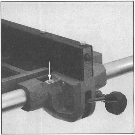

G1022Z Fence
The fence must engage and square up on the front rail before the rear clamp engages the back rail. In essence, the rear clamp should act as a secondary mechanism for maintaining fence position. When adjusted correctly, the lever lock should only begin to apply pressure on the back rail over the last one third of its stroke. To adjust the fence:
- First, make sure the front clamp is engaging the front rail with the lock handle at one half its throw. If the front clamp requires adjustment, loosen the check nut. Figure 30. Turn the adjusting bolt in if the front clamp is too far from the rail , out if it is too close.
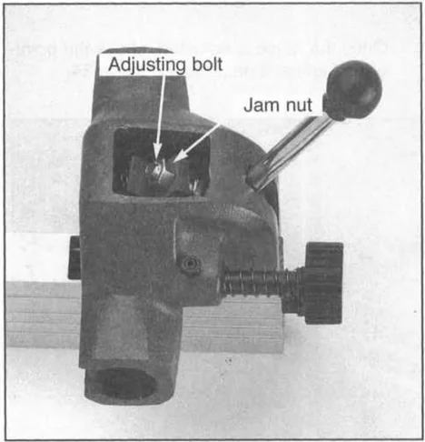
Figure 30. Adjustment points.
-
Now slide the fence along the rail until it is aligned with the edge of the miter slot. Lock the fence down.
-
Loosen the rear lock adjustment (the slotted screw on the front of the fence) until the rear locking lever ceases to engage the rear rail with the fence in the locked position. Figure 31.
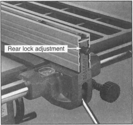
 Figure 32. Adjustment screw locations.
-
Loosen the locking lever until it is approximately two thirds engaged. Make note of its position and lift it up all the way. Tighten the rear adjusting screw until the rear clamp is approximately 1/16" from the rail. Move the lock handle back to its two thirds position. The rear clamp should just be touching the rail. If it is too loose or too tight lift up the handle and turn the adjusting screw in small increments until the clamp is in its proper location. NOTE: Do not turn the adjustment screw unless the lock handle is in the up position. Damage to the clamp shoe will result if this step is not observed.
-
Loosen the locking lever and slide the fence along the rail. Return the fence to its position at the edge of the miter slot and slowly apply pressure to the lever. If adjustments are correct, the fence should square itself before the rear clamp engages. If the rear clamp engages before the fence is squared, loosen the screw one quarter turn and re-test.
Tip – Attach a piece of 3/4" thick hardwood to the blade side of the fence. This will keep thin materials from wedging between the fence and table, and will also protect the fence from coming in contact with the blade when dadoing or ripping thin stock. Figure 33.
 Rip Fence
Auxiliary Wood Fence
Figure 33.
- Once the fence is adjusted, check the pointer and adjust if necessary. Figure 34.
 Figure 34. Pointer.
Table Inserts
The G1022/G1022Z comes with a regular and a dado insert. Figure 35. The standard table insert comes pre-installed and only requires leveling.
-
Lower the blade all the way.
-
Turn the setscrews in or out to adjust the insert flush with the table top. Figure 36. We recommend securing the setscrews in place with a drop of glue on the threads to keep the height adjustment from changing.
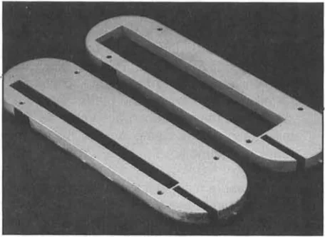
Figure 35.
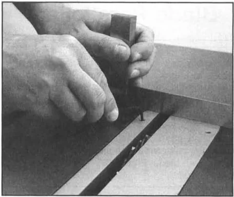
Figure 36.
-
Repeat the procedure for the dado head insert, so it will be properly adjusted when you’re ready to use it.
-
To remove the insert, lift the front up and lift out. Note: The blade will not be exactly centered in the insert slot. This is normal. This positioning allows the blade to tilt a full 45° without hitting the insert. If the blade hits the edge of the insert when raised, the blade is out of alignment.
Blade Parallelism
Your table saw will give the best results if the miter slot is parallel to the blade. If they are not exactly parallel, your cuts and finished work will be lower in quality. To check and adjust miter slot vs. blade parallelism:
- Using an adjustable square, measure the distance between the miter slot and the front of your blade. Figure 37.
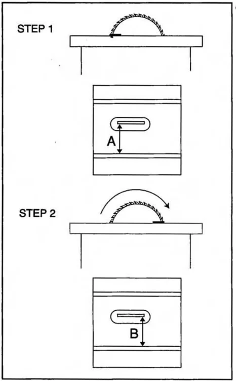
Figure 37.
-
Note the first measurement. Rotate the blade 180° and move the square to the rear of the blade. You may find it helpful to mark your blade with a felt-tip pen at the point where the straightedge and blade meet, as a rotation guide.
-
Compare the measurements. If the difference in measurements is less than 1/32", your blade and table are in acceptable alignment. If the difference is greater, you will need to adjust the table.
-
To adjust blade alignment, remove the motor and the upper half of the saw from the stand. Place it upside down on 4 x 4 blocks to allow the saw blade to rotate freely.
-
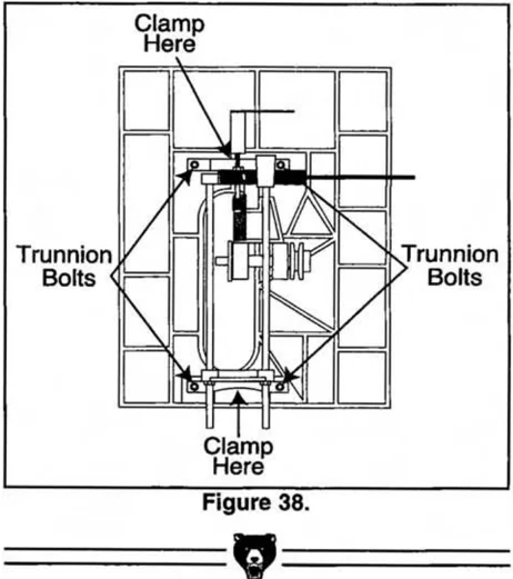
Remove the handwheels and the sheet metal body. The four trunnion bolts can now be loosened. Figure 38. This will allow the trunnion assembly to be shifted to change the alignment between the blade and miter slot. To maintain trunnion assembly as one unit, place a bar clamp across the entire trunnion assembly.
-
Now measure miter slot to blade as in Steps 1 and 2. Move the trunnion assembly until proper alignment has been obtained. Tighten the trunnion bolts and remove the bar clamp.
45° and 90° Stops
The Model G1022/G1022Z is equipped with positive stops at 45° and 90°. When properly adjusted, they provide precise and dependable guides for bevel adjustment. To set these stops:
-
Raise the saw blade to its maximum height by turning the front handwheel clockwise.
-
Set the saw blade at 90° to the table by turning the handwheel at the side of the machine as far as it will go. Caution: Do not force the handwheels when setting the blade height or bevel. If the handwheels offer resistance, do not continue turning until you determine the source of the resistance.
-
Once your blade is set at 90° to the table, place a machinist's square or speed square against the blade and table surface, as shown in Figure 39.
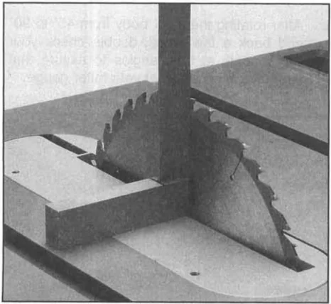
Figure 39.
-
With the square in place, inspect for variation between the blade and square.
-
If a gap exists at either the top or the bottom of the square, loosen lock nut (A) and adjustment bolt (B) indicated in Figure 40.
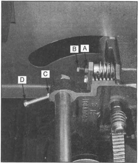
Figure 40.
-
Turn the handwheel until the blade and square are flush from top to bottom.
-
Snug the adjustment screw and tighten the lock nut. Re-check the blade with the square to ensure that you haven’t over tightened the screw.
-
Using the side handwheel, adjust the blade bevel until you hit the 45° positive stop. Check the bevel with your speed square or an adjustable square set to 45°.
-
If variations exist, loosen the lock nut (C) and adjust the stop bolt (D) until your blade and square match. Figure 40.
-
Tighten the lock nut and re-check the bevel by adjusting the blade back to 90°, then back to 45°. Correct again, if necessary.

Worm Gear
The degree of resistance at the blade height handwheel can be adjusted to compensate for wear, or for personal preference. To adjust:
- Loosen the lock nut (A) shown in Figure 41. This will allow the eccentric sleeve that surrounds the worm gear to turn. Although this process can be done with the handwheel in place, you may find it easier to remove it first.
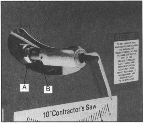
Figure 41.
- As you watch from below, twist the pointer assembly at the front of the saw. As you turn the pointer, you'll see the worm gear move toward and away from the teeth on the front trunnion. Ideally, the worm gear should mesh with the teeth without slop or excess tightness. The process requires a bit of trial and error.
- Once you have found a degree of tightness that you prefer, tighten the lock nut.
- Loosen the setscrew (B) and pivot the pointer back to zero. Retighten the setscrew. Replace the handwheel.
Miter Gauge
To adjust the miter gauge so it is perpendicular to the saw blade:
- Loosen the lock knob on the miter gauge and place a square against the face of the miter body and the blade.
- Adjust the miter body until there is no space between the square and the blade. Tighten the lock knob.
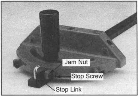
- With the stop link in the up position, loosen the jam nut and adjust the stop screw until it is seated against the stop link. Figure 42.
- Now loosen the setscrew on the left front side of the miter bar, adjust the pointer to 90° and retighten the setscrew.
- To adjust to 45°, follow steps 1-4 using an adjustable square set to 45°.
- After rotating the miter body from 45° to 90° and back a few times, double check your adjustments at both angles to assure that you have accurately set your miter gauge.


SECTION 6: OPERATIONS
Test Run
Once assembly is complete and adjustments are done to your satisfaction, you are ready to test the machine.
Turn on the power supply at the main panel. Press the START button. Make sure that your finger is poised on the STOP button, just in case there's a problem. The table saw should run smoothly, with little or no vibration or rubbing noises. Strange or unnatural noises should be investigated and corrected before operating the machine further.
WARNING: DO NOT attempt to investigate or adjust the machine while it is running. Wait until the machine is turned off, unplugged and all working parts have come to a rest before you do anything!
If you cannot easily locate the source of an unusual noise or vibration, feel free to contact our service department for help.
If the saw runs smoothly, try cutting a piece of lumber. If a problem exists, stop the machine and review all the adjustments. Call for assistance, if needed.
Blade Selection
Choosing the correct blade for the job is essential for the safe and efficient use of your table saw. Ignoring this important step could result in damage to the saw and serious injury to the operator. Documented below are the most common saw blades and their uses.
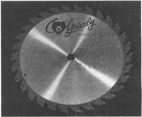
- Rip Blade: Used for cutting with the grain. Typically, rip blades have between 20-30 teeth, a flat-top ground profile and large gullets to allow for large chip removal. Figure 43.

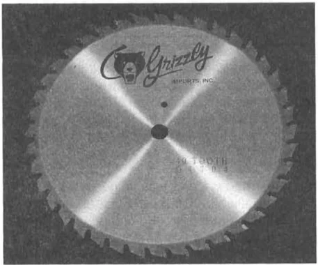
- Cross-cut Blade: Used for cutting across the grain. Cross-cut blades have between 40-100 teeth, alternate top bevel or steep alternate top bevel tooth profiles, small hook angle and a shallow gullet. Figure 44.
- Combination Blade: Used for cutting with and across the grain. A compromise between a rip blade and a cross-cut blade, a combination blade will typically have between 40-80 teeth, an alternate top bevel and flat or alternate top bevel and raker tooth profile. The teeth are arranged in groups of five. The gullets are small and shallow within the groups of five, similar to a cross-cut blade, large and deep between the groups, like a ripping blade. Figure 45.
 Figure 45.
- Plywood Blade: Used for cutting plywood or veneers. A Plywood blade will have 80+ teeth, a steep alternate top bevel tooth pro-file and very shallow gullet. Figure 46.
 Figure 46.
-
Thin-kerf: Most types of saw blades are available in a thin-kerf style. Used primarily to minimize stock wastage. It is recommend-ed thin-kerf blades be used in conjunction with a blade stabilizer to reduce blade wob-ble. Note: Most blade guards/splitters are thicker than most thin-kerf blades. Make sure the stock will pass by the guard/splitter before beginning a cut.
-
Dado Blades: There are two types of dado blades: stack and wobble. Stack dadoes are expensive and time consuming to set up but leave a clean and smooth finish. Stack dadoes are used for fine furniture and cabi-net making. Wobble dadoes are inexpensive and easy to set up, but leave a rough finish.
This section on Blade Selection is by no means comprehensive. Always follow the saw blade manufacturer's recommendations to assure safe and efficient operation of your table saw.

Ripping
Ripping, as shown in Figure 47 refers to cuts which follow the direction of wood grain. The rip fence is used to position and guide work through the cutting edge of the saw blade.
It is essential, for precision cutting, that the stock to be cut be straight and flat. Otherwise, it can bind against the blade, or cut irregularly.
During the cutting operation, the saw guard must be used. The guard has anti-kickback fingers and a splitter that prevents the saw kerf from closing and pinching the blade. When ripping small stock, use a push stick. Do not cut material that is too small to be supported by the table or fence.
When making repeated rip cuts, take time to ensure that the fence is securely in place. A quick measurement of your last ripped board will verify that the cut is still the width you desire.
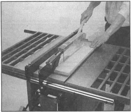
Figure 47.
Crosscutting
Crosscutting means cutting across the grain of the wood. In wood products without grain (i.e. MDF, particleboard) it simply means cutting across the width of the stock.
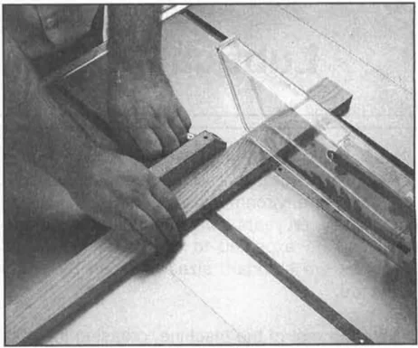
Crosscuts are made with the miter gauge. There are two miter gauge slots in the table top. Use the one that works best for the piece being crosscut. To make a crosscut using the miter gauge:
- Inspect the board for soundness. You do not necessarily need a square edge to crosscut with accuracy.
- Move the rip fence completely out of the way.
- Turn on the saw and allow it to come to full speed.
- Hold the workpiece firmly against the face of the miter gauge and ease it into the blade. Figure 43.
- Turn off the saw and allow the blade to come to a full stop.
SECTION 7: MAINTENANCE
General
Make a habit of inspecting your saw each time you use it. Check for the following conditions and repair or replace when necessary.
- Loose mounting bolts.
- Worn switch.
- Worn or damaged cords and plugs.
- Dull or damaged blade.
- Poor fence adjustment.
- Poor blade adjustment.
- Any other condition that could hamper the safe operation of this machine.
Lubrication
Shielded and pre-lubricated ball bearings require no lubrication for the life of the bearings. In a continuous-use environment, expect the bearings to last for several years. With intermittent use, bearings can be expected to last much longer. All bearings are standard sizes and can be easily replaced.
As for the rest of the machine, greasing the rack and pinion is all that's necessary to keep it in top working condition. Before applying, however, wipe off any sawdust with a cloth or towel. Ensure that no grease gets on pulleys or V-belts.
Table
The table and other non-painted surfaces on the Model G1022/G1022Z should be protected against rust and pitting. Wiping the saw clean after every use ensures that moisture from saw-dust isn't allowed to trap moisture against bare metal surfaces.
Some woodworkers recommend using automotive paste wax on exposed steel and cast iron surfaces. The wax provides a layer of protection, as well as reducing friction between lumber and the table, making cuts faster and smoother. Avoid waxes that contain silicone or other synthetic ingredients. These materials can find their way into lumber that's being cut, and can make staining and finishing difficult. If you use paste wax, make sure that it's 100% Carnauba wax.
V-belt
Since the weight of the motor provides a constant source of tension for the V-belt, there is no need to adjust the tension.
If the V-belt is worn, it should be replaced. Worn or damaged V-belts can cause your saw to vibrate during operation, and a broken belt could mean danger if it is thrown from a running machine. If you have any doubts about the quality of your V-belt, replace it.
As part of your maintenance schedule, you might consider dressing your belt with one of the many belt dressing sprays on the market.
SECTION 8: CLOSURE
The following pages contain G1022 parts diagram, parts list, G1022Z parts diagram, parts list, general machine specifications, troubleshooting guide and Warranty/Return information for your Model G1022/G1022Z 10" table saw.
If you need parts or help in assembling your machine, or if you need operational information, we encourage you to call our Service Department. Our trained service technicians will be glad to help you.
If you have comments dealing specifically with this manual, please write to our Bellingham, Washington location using the address in the Introduction. The specifications, drawings, and photographs illustrated in this manual represent the Model G1022/G1022Z as supplied when the manual was prepared. However, due to Grizzly's policy of continuous improvement, changes may be made at any time with no obligation on the part of Grizzly. Whenever possible, though, we send manual updates to all owners of a particular tool or machine. Should you receive one, add the new information to this manual and keep it for reference.
We have included some important safety measures that are essential to this machine's operation. While most safety measures are generally universal, Grizzly reminds you that each workshop is different and safety rules should be considered as they apply to your specific situation.
We recommend you keep a copy of our current catalog for complete information regarding Grizzly's warranty and return policy. If you need additional technical information relating to this machine, or if you need general assistance or replacement parts, please contact our Service Department listed in the introduction.
Additional information sources are necessary to realize the full potential of this machine. Trade journals, woodworking magazines, and your local library are good places to start.
WARNING! Like all power tools, there is danger associated with the Model G1022/G1022Z 10" table saw. Use the tool with respect and caution to lessen the possibility of mechanical damage or operator injury. If normal safety precautions are overlooked or ignored, injury to the operator or others in the area is likely.
The Model G1022/G1022Z was specifically designed for ripping and crosscutting operations. DO NOT MODIFY AND/OR USE THIS SAW FOR ANY OTHER PURPOSE. Modifications or improper use of this tool will void the warranty. If you are confused about any aspect of this machine, DO NOT use it until you have answered all your questions.
G1022
G1022
G1022
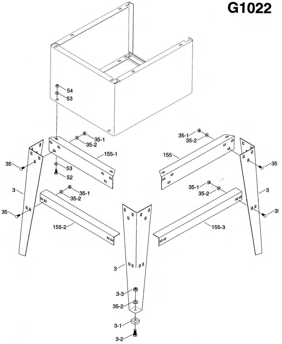
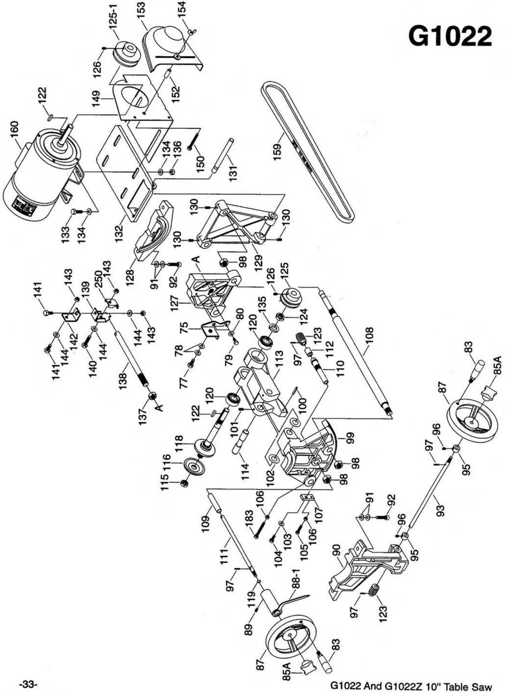
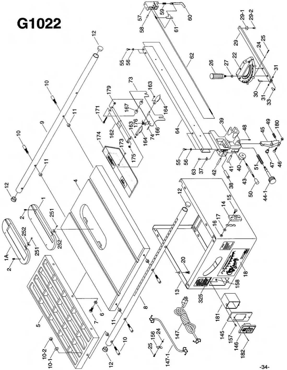
G1022 PARTS LIST
| REF | PART # | DESCRIPTION |
|---|---|---|
| 1 | P1022001 | TABLE INSERT |
| 1A | P1022001-A | DADO INSERT |
| 2 | PSS04M | SETSCREW M6-1.0 x 12 |
| 3 | P1022Z003 | STAND LEG |
| 3-1 | P1022Z003-1 | FOOT |
| 3-2 | P1022Z003-2 | HEX BOLT M10-1.5 x 25mm |
| 3-3 | PN02M | HEX NUT M10-1.5 |
| 4 | P1022004 | TABLE |
| 5 | G1193 | EXTENSION WING |
| 6 | P1022006 | SPECIAL WASHER |
| 7 | PB01M | HEX BOLT M10-1.5 x 30mm |
| 8 | P1022008 | FRONT GUIDE RAIL |
| 9 | P1022009 | REAR GUIDE RAIL |
| 10 | P1022010 | SPECIAL RAIL BOLT |
| 10-1 | PW04M | FLAT WASHER 10mm |
| 10-2 | PN01M | HEX NUT M10-1.5 |
| 11 | P1022011 | RAIL SPACER |
| 12 | P1022012 | GUIDE RAIL PLUG |
| 13 | P1022013 | CABINET |
| 14 | P1022014 | GEAR BRACKET |
| 15 | PB03M | HEX BOLT M8-1.25 x 16mm |
| 16 | PN02M | HEX NUT M10-1.25 |
| 17 | PW01M | FLAT WASHER 8mm |
| 18 | P1022018 | TILTING SCALE |
| 20 | PB03M | HEX BOLT M8-1.25 x 16mm |
| 21 | PW01M | FLAT WASHER 8mm |
| 22 | P1022022 | MITER BODY |
| 24 | PN04M | HEX NUT M4-0.7 |
| 25 | PS01M | PHLP HD SCR M4-0.7 x 18 |
| 26 | P1022026 | HAND KNOB |
| 27 | P1022027 | FIBER WASHER |
| 29 | P1022029 | MITER BAR |
| 29-1 | P1022029-1 | T-SLOT WASHER |
| 29-2 | PFH04M | FLAT HEAD SCR M6-1.0 x 8 |
| 30 | P1022030 | ANGLE POINTER |
| 31 | PSS02M | SETSCREW M6-1.0 x 6mm |
| 33 | P1022033 | STOP LINK |
| 35 | PCB01M | CARR BOLT M8-1.25x20mm |
| 35-1 | PN03M | HEX NUT M8-1.25 |
| 35-2 | PW01M | FLAT WASHER 8mm |
| 37 | P1022037 | WIDTH POINTER |
| 38 | P1022038 | FENCE ADJUSTER |
| 39 | P1022039 | FRONT CLAMP |
| REF | PART # | DESCRIPTION |
|---|---|---|
| 40 | P1022040 | ECCENTRIC |
| 41 | P1022041 | SHAFT FOR ECCENTRIC |
| 42 | P1022042 | SHAFT FOR CLAMP |
| 43 | P1022043 | LOCK LEVER |
| 44-1 | P1022044-1 | PINION W/ KNOB |
| 45 | P1022045 | CLAMP SHOE |
| 46 | P1022046 | ADJUSTING BOLT |
| 47 | P1022047 | SHAFT BUSHING |
| 48 | PSS02M | SET SCREW M6-1.0 x 6 |
| 49 | P1022049 | SPRING |
| 50 | P1022050 | HAND KNOB |
| 51 | P1022051 | SPRING |
| 52 | PB03M | HEX BOLT M8-1.25 x 16mm |
| 53 | PW01M | FLAT WASHER 8mm |
| 54 | PN03M | HEX NUT M8-1.25 |
| 55 | PB06M | HEX BOLT M8-1.25 x 12mm |
| 56 | PW01M | FLAT WASHER 8mm |
| 57 | P1022057 | BLOCK |
| 58 | P1022058 | PIN |
| 59 | P1022059 | SPRING |
| 60 | P1022060 | CLAMP HOOK |
| 61 | P1022061 | LEVER |
| 62 | P1022062 | LOCK LINK |
| 63 | PS05M | PHLP HD SCR M5-0.8 x 8 |
| 64 | P1022064 | FENCE |
| 73 | P1022073 | SPLITTER |
| 74 | PRP20M | ROLL PIN 4 x 22 |
| 75 | P1022075 | BRACKET |
| 77 | PB03M | HEX BOLT M8-1.25 x 16mm |
| 78 | PW01M | FLAT WASHER 8mm |
| 79 | PB02M | HEX BOLT M6-1.0 x 12mm |
| 80 | PW03M | FLAT WASHER 6mm |
| 83 | P1022083 | HANDLE |
| 85A | P1022085A | KNOB |
| 87 | P1022087 | HANDWHEEL |
| 88-1 | P1022088-1 | POINTER ASSEMBLY |
| 89 | PSS03M | SETSCREW M6-1.0 x 8mm |
| 90 | P1022090 | FRONT BRACKET |
| 91 | PW01M | FLAT WASHER 8mm |
| 92 | PSB13M | CAP SCREW M8-1.25x30mm |
| 93 | P1022093 | ANGLE WORM SHAFT |
| 95 | P1022095 | COLLAR |
| 96 | PSS02M | SETSCREW M6-1.0 x 6mm |
G1022 And G1022Z □□" Table Saw
G1022 PARTS LIST
| REF | PART # | DESCRIPTION |
|---|---|---|
| 97 | PRP02M | ROLL PIN 3 x 16 |
| 98 | PN05M | HEX NUT M16-1.5 |
| 99 | P1022090 | FRONT TRUNNION |
| 100 | PRP02M | ROLL PIN 5 X 24 |
| 101 | PSS04M | SET SCREW M6 - 1.0 x12mm |
| 102 | P1022102 | WAVY WASHER |
| 103 | PW03M | FLAT WASHER 6mm |
| 104 | PB08M | HEX BOLT M6-1.0 x 20mm |
| 105 | PB10M | HEX BOLT M6-1.0 x 25mm |
| 106 | PN01M | HEX NUT M6-1.0 |
| 107 | P1022107 | SET PLATE |
| 108 | P1022108 | LINKING BAR |
| 109 | P1022109 | SPACER |
| 110 | P1022110 | ECCENTRIC SLEEVE |
| 111 | P1022111 | WORM SHAFT |
| 112 | P1022112 | SPACER |
| 113 | P1022113 | ARBOR BRACKET |
| 114 | P1022114 | ARBOR BRACKET PIN |
| 115 | P1022115 | ARBOR NUT |
| 116 | P1022116 | FLANGE |
| 118 | P1022118 | BLADE ARBOR |
| 119 | PR01M | EXT RETAINING RING 10MM |
| 120 | P6203 | BEARING 6203-2RS |
| 122 | PK01M | KEY 5 x 5 x 22mm |
| 123 | P1022123 | WORM |
| 123-1 | P1022123-1 | ROLL PIN |
| 124 | P1022124 | HEX NUT |
| 125 | P1022125 | SPINDLE PULLEY |
| 125-1 | P1022125-1 | MOTOR PULLEY |
| 126 | PSS03M | SETSCREW M6-1.0 x 12mm |
| 127 | P1022127 | REAR TRUNNION |
| 128 | P1022128 | REAR BRACKET |
| 129 | P1022129 | MOTOR BRACKET |
| 130 | PSS04M | SETSCREW M6-1.0 x 12mm |
| 131 | P1022131 | MOTOR PLATE ROD |
| 132 | P1022132 | MOTOR PLATE |
| 133 | PB07M | HEX BOLT M8-1.25 x 25mm |
| 134 | PW01M | FLAT WASHER 8mm |
| 135 | PLW06 | LOCK WASHER 5/8" |
| 136 | PN03M | HEX NUT M8-1.25 |
| 137 | PN05M | HEX NUT M16-1.5 |
| 138 | P1022138 | SHAFT |
| 139 | P1022139 | BRACKET |
| 140 | PB26M | HEX BOLT M8-1.25 x 30mm |
| REF | PART # | DESCRIPTION |
|---|---|---|
| 141 | PB03M | HEX BOLT M8-1.25 x 16mm |
| 142 | P1022142 | CONNECTING PLATE |
| 143 | PN03M | HEX NUT M8-1.25 |
| 144 | PW01M | FLAT WASHER 8mm |
| 145 | P1022145 | SWITCH BRACKET |
| 146 | P1022146 | SWITCH |
| 147 | PWRCRD110L | PWR CRD 16G X 3W 73"L |
| 147-1 | PWRCRD110S | PWR CRD 16G X 3W 24"L |
| 148 | P1022148 | SPANNER WRENCH |
| 149 | P1022149 | PULLEY GUARD BRACKET |
| 150 | PB10 | HEX BOLT 1/4"-20 x 2" |
| 152 | P1022152 | SLEEVE |
| 153 | P1022153 | PULLEY COVER |
| 154 | PWN02 | WINGNUT 1/4"-20 |
| 155 | P1022Z155 | UPPER BRACKET - LONG |
| 155-1 | P1022Z155-1 | UPPER BRACKET - SHORT |
| 155-2 | P1022Z155-2 | LOWER BRACKET - SHORT |
| 155-3 | P1022Z155-3 | LOWER BRACKET - LONG |
| 156 | P1022156 | WIRE CLAMP |
| 157 | PS09M | PHLP HD SCR M5-0.8 x 12 |
| 158 | PN06M | HEX NUT M5-0.8 |
| 159 | PVA43 | V-BELT A-43 |
| 160 | P1022160 | MOTOR 1-1/2 H.P. |
| 161 | P1022161 | STRAIN RELIEF |
| 162 | P1022162 | SUPPORTING ARM |
| 163 | P1022163 | RETAINER |
| 164 | P1022164 | PAWL |
| 166 | P1022166 | PIN |
| 167 | P1022167 | SPACER |
| 171 | P1022171 | HEX BOLT M6-1.0 x 40mm |
| 173 | P1022173 | PIVOT PIN |
| 174 | P1022174 | GUARD |
| 175 | P1022175 | RETAINER |
| 176 | P1022176 | SPRING |
| 179 | PLN03M | LOCK NUT M6-1.0 |
| 180 | PN02M | HEX NUT M10-1.5 |
| 181 | P1022181 | SWITCH GUARD |
| 182 | P1022182 | SCREW |
| 183 | P1022183 | HEX BOLT M6-1.0 x 50mm |
| 250 | P1022250 | CLAMP |
| 251 | PS05M | PHILIP HD SCR M5-0.8 X 8 |
| 252 | P1022252 | SPRING |
| 325 | P1022325 | WARNING LABEL |
G1022Z
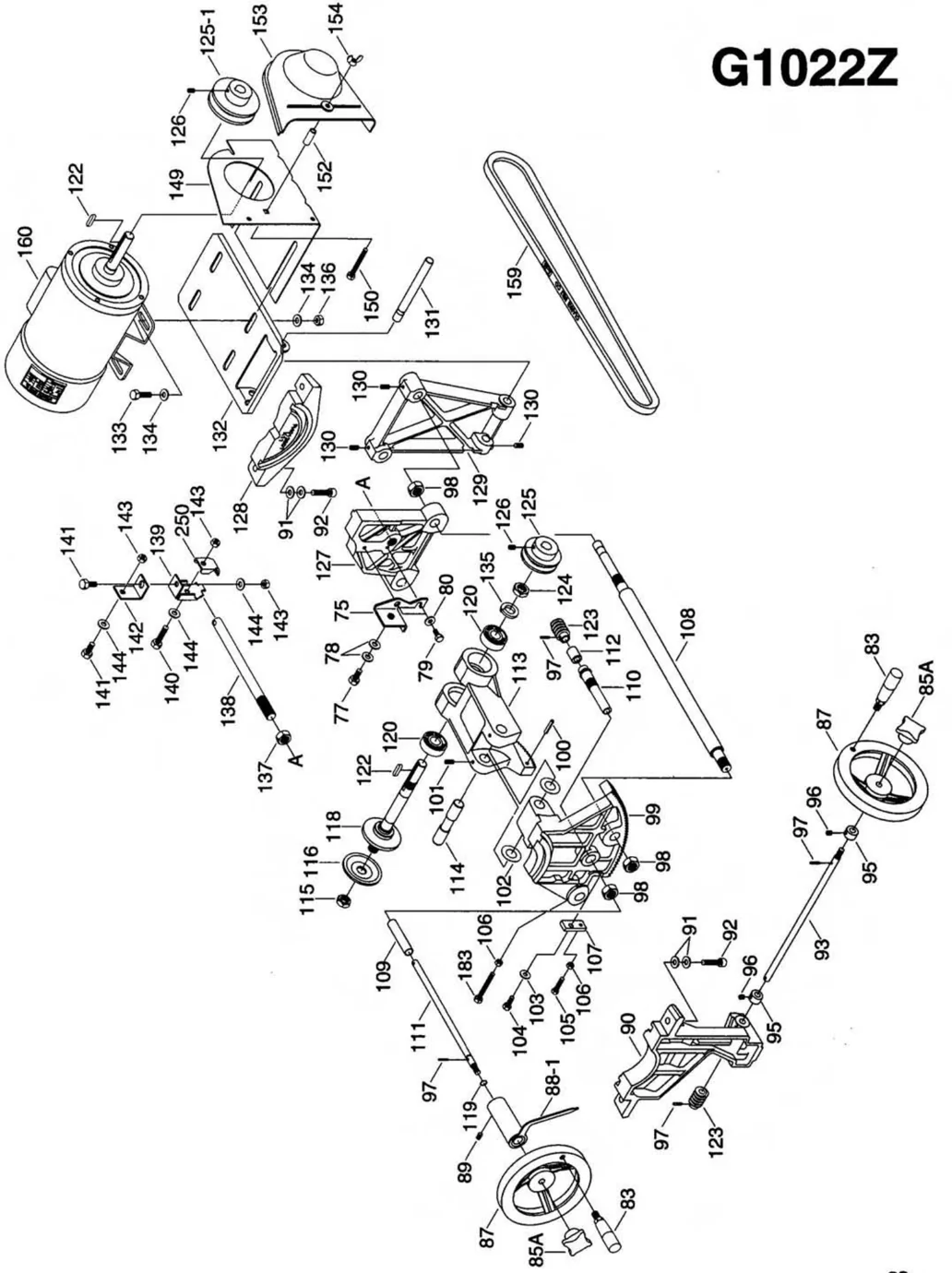
G1022Z
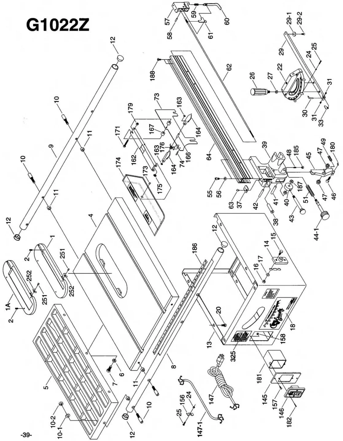
G1022Z
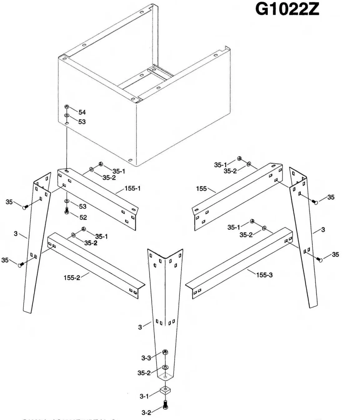
G1022Z PARTS LIST
| REF | PART # | DESCRIPTION |
|---|---|---|
| 1 | P1022001 | TABLE INSERT |
| 1A | P1022001-A | DADO INSERT |
| 2 | PSS04M | SETSCREW M6-1.0 x 12 |
| 3 | P1022003 | STAND LEG |
| 3-1 | P1022Z003-1 | FOOT |
| 3-2 | P1022Z003-2 | HEX BOLT M10-1.5 x 25mm |
| 3-3 | PN02M | HEX NUT M10-1.5 |
| 4 | P1022004 | TABLE |
| 5 | G1193 | EXTENSION WING |
| 6 | P1022006 | SPECIAL WASHER |
| 7 | PB01M | HEX BOLT M10-1.5 x 30mm |
| 8 | P1022Z008 | FRONT GUIDE RAIL |
| 9 | P1022009 | REAR GUIDE RAIL |
| 10 | P1022010 | SPECIAL RAIL BOLT |
| 10-1 | PW04M | FLAT WASHER 10mm |
| 10-2 | PN01M | HEX NUT M10-1.5 |
| 11 | P1022011 | RAIL SPACER |
| 12 | P1022012 | GUIDE RAIL PLUG |
| 13 | P1022013 | CABINET |
| 14 | P1022014 | GEAR BRACKET |
| 15 | PB03M | HEX BOLT M8-1.25 x 16mm |
| 16 | PN03M | HEX NUT M8-1.25 |
| 17 | PW01M | FLAT WASHER 8mm |
| 18 | P1022018 | TILTING SCALE |
| 20 | PB03M | HEX BOLT M8-1.25 x 16mm |
| 21 | PW01M | FLAT WASHER 8mm |
| 22 | P1022022 | MITER BODY |
| 24 | PN04M | HEX NUT M4-0.7 |
| 25 | PS01M | PHLP HD SCREW M4 - 0.7 x 18 |
| 26 | P1022026 | HAND KNOB |
| 27 | P1022027 | FIBER WASHER |
| 29 | P1022029 | MITER BAR |
| 29-1 | P1022029-1 | T-SLOT WASHER |
| 29-2 | PFH04M | FLAT HEAD SCREW M6-1.0 x 8 |
| 30 | P1022030 | ANGLE POINTER |
| 31 | PSS02M | SETSCREW M6-1.0 x 6mm |
| 33 | P1022033 | STOP LINK |
| 35 | PCB01M | CARR. BOLT M8-1.25 x 20mm |
| 35-1 | PN03M | HEX NUT M8-1.25 |
| 35-2 | PW01M | FLAT WASHER 8mm |
| 37 | P1022Z037 | WIDTH POINTER |
| 38 | P1022038 | FENCE ADJUSTER |
| 39 | P1022Z039 | FRONT CLAMP |
| 40 | P1022040 | ECCENTRIC |
| REF | PART # | DESCRIPTION |
|---|---|---|
| 41 | P1022041 | SHAFT FOR ECCENTRIC |
| 42 | P1022042 | SHAFT FOR CLAMP |
| 43 | P1022043 | LOCK LEVER |
| 44-1 | P1022044-1 | PINION W/ KNOB |
| 45 | P1022Z045 | CLAMP SHOE |
| 46 | P1022046 | ADJUSTING BOLT |
| 47 | P1022Z047 | SHAFT BUSHING |
| 48 | PSS02M | SET SCREW M6-1.0 x 6 |
| 49 | P1022049 | SPRING |
| 51 | P1022051 | SPRING |
| 52 | PB03M | HEX BOLT M8-1.25 x 16mm |
| 53 | PW01M | FLAT WASHER 8mm |
| 54 | PN03M | HEX NUT M8-1.25 |
| 55A | PSB52M | CAP SCREW M8-1.25 x 12mm |
| 56 | PW01M | FLAT WASHER 8mm |
| 57 | P1022057 | BLOCK |
| 58 | P1022058 | PIN |
| 59 | P1022059 | SPRING |
| 60 | P1022060 | CLAMP HOOK |
| 61 | P1022061 | LEVER |
| 62 | P1022062 | LOCK LINK |
| 63 | PS05M | PHLP HD SCREW M5-0.8 x 8 |
| 64 | P1022Z064 | FENCE |
| 73 | P1022073 | SPLITTER |
| 74 | PRP20M | ROLL PIN 4 x 22 |
| 75 | P1022075 | BRACKET |
| 77 | PB03M | HEX BOLT M8-1.25 x 16mm |
| 78 | PW01M | FLAT WASHER 8mm |
| 79 | PB02M | HEX BOLT M6-1.0 x 12mm |
| 80 | PW03M | FLAT WASHER 6mm |
| 83 | P1022083 | HANDLE |
| 85A | P1022085A | KNOB |
| 87 | P1022087 | HANDWHEEL |
| 88-1 | P1022088-1 | POINTER ASSEMBLY |
| 89 | PSS03M | SETSCREW M6-1.0 x 8mm |
| 90 | P1022090 | FRONT BRACKET |
| 91 | PW01M | FLAT WASHER 8mm |
| 92 | PSB13M | CAP SCREW M8-1.25 x 30mm |
| 93 | P1022093 | ANGLE WORM SHAFT |
| 95 | P1022095 | COLLAR |
| 96 | PSS02M | SETSCREW M6-1.0 x 6mm |
| 97 | PRP02M | ROLL PIN 3 x 16 |
| 98 | PN05M | HEX NUT M16-1.5 |
| 99 | P1022099 | FRONT TRUNNION |
G1022 And G1022Z □□" Table Saw
G1022Z PARTS LIST
| REF | PART # | DESCRIPTION |
|---|---|---|
| 100 | PRP02M | ROLL PIN 5 X 24 |
| 101 | P4404M | SET SCREW M6 - 1.0 x 12mm |
| 102 | P1022102 | WAVY WASHER |
| 103 | PW03M | FLAT WASHER 6mm |
| 104 | PB08M | HEX BOLT M6-1.0 x 20mm |
| 105 | PB10M | HEX BOLT M6-1.0 x 25mm |
| 106 | PN01M | HEX NUT M6-1.0 |
| 107 | P1022107 | SET PLATE |
| 108 | P1022108 | LINKING BAR |
| 109 | P1022109 | SPACER |
| 110 | P1022110 | ECCENTRIC SLEEVE |
| 111 | P1022111 | WORM SHAFT |
| 112 | P1022112 | SPACER |
| 113 | P1022113 | ARBOR BRACKET |
| 114 | P1022114 | ARBOR BRACKET PIN |
| 115 | P1022115 | ARBOR NUT |
| 116 | P1022116 | FLANGE |
| 118 | P1022118 | BLADE ARBOR |
| 120 | P6203 | BEARING 6203-2RS |
| 122 | PK01M | KEY 5 x 5 x 22mm |
| 123 | P1022123 | WORM |
| 123-1 | P1022123-1 | ROLL PIN |
| 124 | P1022124 | HEX NUT |
| 125 | P1022125 | SPINDLE PULLEY |
| 125-1 | P1022125-1 | MOTOR PULLEY |
| 126 | PSS03M | SETSCREW M6-1.0 x 12mm |
| 127 | P1022127 | REAR TRUNNION |
| 128 | P1022128 | REAR BRACKET |
| 129 | P1022129 | MOTOR BRACKET |
| 130 | PSS04M | SETSCREW M6-1.0 x 12mm |
| 131 | P1022131 | MOTOR PLATE ROD |
| 132 | P1022132 | MOTOR PLATE |
| 133 | PB07M | HEX BOLT M8-1.25 x 25mm |
| 134 | PW01M | FLAT WASHER 8mm |
| 135 | PLW06 | LOCK WASHER 5/8" |
| 136 | PN03M | HEX NUT M8-1.25 |
| 137 | PN05M | HEX NUT M16-1.5 |
| 138 | P1022138 | SHAFT |
| 139 | P1022139 | BRACKET |
| 140 | PB26M | HEX BOLT M8-1.25 x 30mm |
| 141 | PB03M | HEX BOLT M8-1.25 x 16mm |
| 142 | P1022142 | CONNECTING PLATE |
| 143 | PN03M | HEX NUT M8-1.25 |
| 144 | PW01M | FLAT WASHER 8mm |
| REF | PART # | DESCRIPTION |
|---|---|---|
| 145 | P1022145 | SWITCH BRACKET |
| 146 | P1022146 | SWITCH |
| 147 | P1022147 | POWER CORD |
| 147-1 | P1022147-1 | MOTOR CORD |
| 148 | P1022148 | SPANNER WRENCH |
| 149 | P1022149 | PULLEY GUARD BRACKET |
| 150 | PB10 | HEX BOLT 1/4"-20 x 2" |
| 150 | PB10 | HEX BOLT 1/4"-20 x 2" |
| 152 | P1022152 | SLEEVE |
| 153 | P1022153 | PULLEY COVER |
| 154 | PWN02 | WINGNUT 1/4"-20 |
| 155 | P1022Z155 | UPPER BRACKET - LONG |
| 155-1 | P1022Z155-1 | UPPER BRACKET - SHORT |
| 155-2 | P1022Z155-2 | LOWER BRACKET - SHORT |
| 155-3 | P1022Z155-3 | LOWER BRACKET - LONG |
| 156 | P1022156 | WIRE CLAMP |
| 157 | PS09M | PHLP HD SCREW M5-0.8 x 12 |
| 158 | PN06M | HEX NUT M5-0.8 |
| 159 | PVA43 | V-BELT A-43 |
| 160 | P1022160 | MOTOR 1-1/2 H.P. |
| 161 | P1022161 | STRAIN RELIEF(Not Shown) |
| 162 | P1022162 | SUPPORTING ARM |
| 163 | P1022163 | RETAINER |
| 164 | P1022164 | PRAWL |
| 166 | P1022166 | PIN |
| 167 | P1022167 | SPACER |
| 171 | P1022171 | HEX BOLT M6-1.0 x 40mm |
| 173 | P1022173 | PIVOT PIN |
| 174 | P1022174 | GUARD |
| 175 | P1022175 | RETAINER |
| 176 | P1022176 | SPRING |
| 179 | PLN03M | LOCK NUT M6-1.0 |
| 180 | PN02M | HEX NUT M10-1.5 |
| 181 | P1022181 | SWITCH GUARD |
| 182 | P1022182 | SCREW |
| 183 | P1022183 | HEX BOLT M6-1.0 x 50mm |
| 185 | PN01M | HEX NUT M6-1.0 |
| 186 | P1022Z186 | SCALE |
| 187 | P1022Z187 | SPACER |
| 188 | P1022Z188 | FLAT HD SCR M8-1.25 x 12 |
| 250 | P1022250 | CLAMP |
| 251 | PS05M | PHLIP HD SCR M5-0.8 X 8 |
| 252 | P1022252 | SPRING |
| 325 | P1022325 | WARNING LABEL |
G1022 Machine Data
- Design Type ........ 10" Tilting Arbor Contractor Style
Overall Dimensions:
- Table Height ........ 37-1/8"
- Table Size ........ 27-1/8" D x 20-1/8" W
- Size With Extensions ........ 27-1/8" D x 40-5/8" W
- Overall Dimensions – With Wings and Guide Bars ........ 48"W x 46"D
- Weight (Net) ........ 230 lbs.
- Weight (Shipping) ........ 255 lbs.
Construction:
- Table ........ Ground Cast Iron
- Stand ........ Pre-formed Steel
- Miter Gauge ........ Aluminum / Steel
- Trunnions ........ Cast Iron
- Bearings ........ Shielded and Lubricated-For-Life / Ball
- Fence ........ Lock Front and Back with Micro-Adjustment Knob
- Guard ........ Steel
Cutting Capacity:
- Maximum Blade Diameter ........ 10"
- Maximum Depth of Cut at 90° ........ 3-1/8"
- Maximum Depth of Cut at 45° ........ 2-1/8"
- Maximum Rip to Right of Blade (Standard) ........ 24"
- Maximum Rip to Right of Blade (Optional Extension Tubes) 48"
- Maximum Rip to Left of Blade ........ 11"
- Distance from Front of Table to Center of Blade ........ 17-1/4"
- Distance from Front of Table to Front of Blade ........ 12-1/2"
- Maximum Width of Dado Cut ........ □3/16"
Motor:
- Type ........ TEFC Capacitor Start Induction
- Horsepower ........ 1-1/2 H.P.
- Phase / Cycle ........ Single Phase / 60 HZ
- Voltage ........ 110V / 220V
- Amps ........ 16@110V / 8@220V
- RPM ........ 60Hz / 3450 RPM
- Power Transfer ........ Belt Drive
- Switch ........ ON / OFF Push-Button
Arbor:
- Diameter ........ 5/8"
- Speed ........ 4,700 R.P.M.
Optional Equipment:
- Model G1187 ........ 70" Extension Tubes
- Model G1193 ........ Extra Cast-Iron Extension Wing
- Model G2480 ........ Dust Exhaust Hood
Specifications, while deemed accurate, are not guaranteed.
-43- G1022 And G1022Z 10" Table Saw
G1022Z Machine Data
- Design Type ........ 10" Tilting Arbor Contractor Style
Overall Dimensions:
- Table Height ........ 37-1/8"
- Table Size ........ 27-1/8" D x 20-1/8" W
- Size With Extensions ........ 27-1/8" D x 40-5/8" W
- Overall Dimensions – With Wings and Guide Bars ........ 48"W x 46"D
- Weight (Net) ........ 230 lbs.
- Weight (Shipping) ........ 255 lbs.
Construction:
- Table ........ Ground Cast Iron
- Stand ........ Pre-formed Steel
- Miter Gauge ........ Aluminum / Steel
- Trunnions ........ Cast Iron
- Bearings ........ Shielded and Lubricated-For-Life / Ball
- Fence ........ Lock Front and Back with Micro-Adjustment Knob
- Guard ........ Steel
Cutting Capacity:
- Maximum Blade Diameter ........ 10"
- Maximum Depth of Cut at 90° ........ 3-1/8"
- Maximum Depth of Cut at 45° ........ 2-1/8"
- Maximum Rip to Right of Blade (Standard) ........ 24"
- Maximum Rip to Right of Blade (Optional Extension Tubes) ........ 48"
- Maximum Rip to Left of Blade ........ 11"
- Distance from Front of Table to Center of Blade ........ 17-1/4"
- Distance from Front of Table to Front of Blade ........ 12-1/2"
- Maximum Width of Dado Cut ........ □3/16"
Motor:
- Type ........ TEFC Capacitor Start Induction
- Horsepower ........ 1-1/2 H.P.
- Phase / Cycle ........ Single Phase / 60 HZ
- Voltage ........ 110V / 220V
- Amps ........ 16@110V / 8@220V
- RPM ........ 60Hz / 3450 RPM
- Power Transfer ........ Belt Drive
- Switch ........ ON / OFF Push-Button
Arbor:
- Diameter ........ 5/8"
- Speed ........ 4,700 R.P.M.
Optional Equipment:
- Model G1187 ........ 70" Extension Tubes
- Model G1193 ........ Extra Cast-Iron Extension Wing
- Model G2480 ........ Dust Exhaust Hood
Specifications, while deemed accurate, are not guaranteed.
TROUBLESHOOTING
| 1. Motor will not start | 1. Saw not plugged in2. Circuit breaker tripped or fuse blown3. Cord damaged4. On/off switch defective |
|---|---|
| 2. Trips circuit breaker frequently | 1. Extension cord too light or too long2. Feeding stock too fast3. Blade is dull or warped4. Fence misaligned causing blade to bind5. Circuit under powered |
| 3. Inaccurate 45° and 90° rip cuts | 1. Positive stops not adjusted correctly2. Angle pointer not set correctly |
| 4. Blade binds when ripping | 1. Rip fence not parallel with blade |
| 5. Wood binds on splitter | 1. Splitter not aligned with blade |
| 6. Unsatisfactory cuts | 1. Dull blade2. Blade mounted backwards3. Gum or pitch on blade4. Wrong blade for work being done |
| 7. Blade will not come up to speed | 1. Extension cord too light or too long2. Motor not wired correctly3. Defective starting capacitor |
| 8. Excessive vibration | 1. Stand bolts loose2. Uneven floor3. Bad V-belt4. V-belt too long5. Damaged blade6. Pulley bent or out of balance7. Raising mechanism has too much play |
| 9. Fence binds on rails | 1. Front clamp not adjusted properly2. Fence rails not parallel |
| 10. Blade does not raise or tilt freely | 1. Raising mechanism adjusted too tight2. Sawdust in raising/tilting mechanism3. Hand wheel lock knobs locked down |
-45- G1022 And G1022Z 10" Table Saw
WARRANTY AND RETURNS
Grizzly Imports, Inc. warrants every product it sells for a period of 1 year to the original purchaser from the date of purchase. This warranty does not apply to defects due directly or indirectly to misuse, abuse, negligence, accidents, repairs or alterations or lack of maintenance. This is Grizzly's sole written warranty and any and all warranties that may be implied by law, including any merchantability or fitness, for any particular purpose, are hereby limited to the duration of this written warranty. We do not warrant or represent that the merchandise complies with the provisions of any law or acts unless the manufacturer so warrants. In no event shall Grizzly's liability under this warranty exceed the purchase price paid for the product and any legal actions brought against Grizzly shall be tried in the State of Washington, County of Whatcom.
We shall in no event be liable for death, injuries to persons or property or for incidental, contingent, special, or consequential damages arising from the use of our products.
To take advantage of this warranty, contact us by mail or phone and give us all the details. We will then issue you a "Return Number", which must be clearly posted on the outside as well as the inside of the carton. We will not accept any item back without this number. Proof of purchase must accompany the merchandise.
The manufacturers reserve the right to change specifications at any time because they constantly strive to achieve better quality equipment. We make every effort to ensure that our products meet high quality and durability standards and we hope you never need to use this warranty.
Please feel free to write or call us if you have any questions about the machine or the manual.
Thank you again for your business and continued support. We hope to serve you again soon.
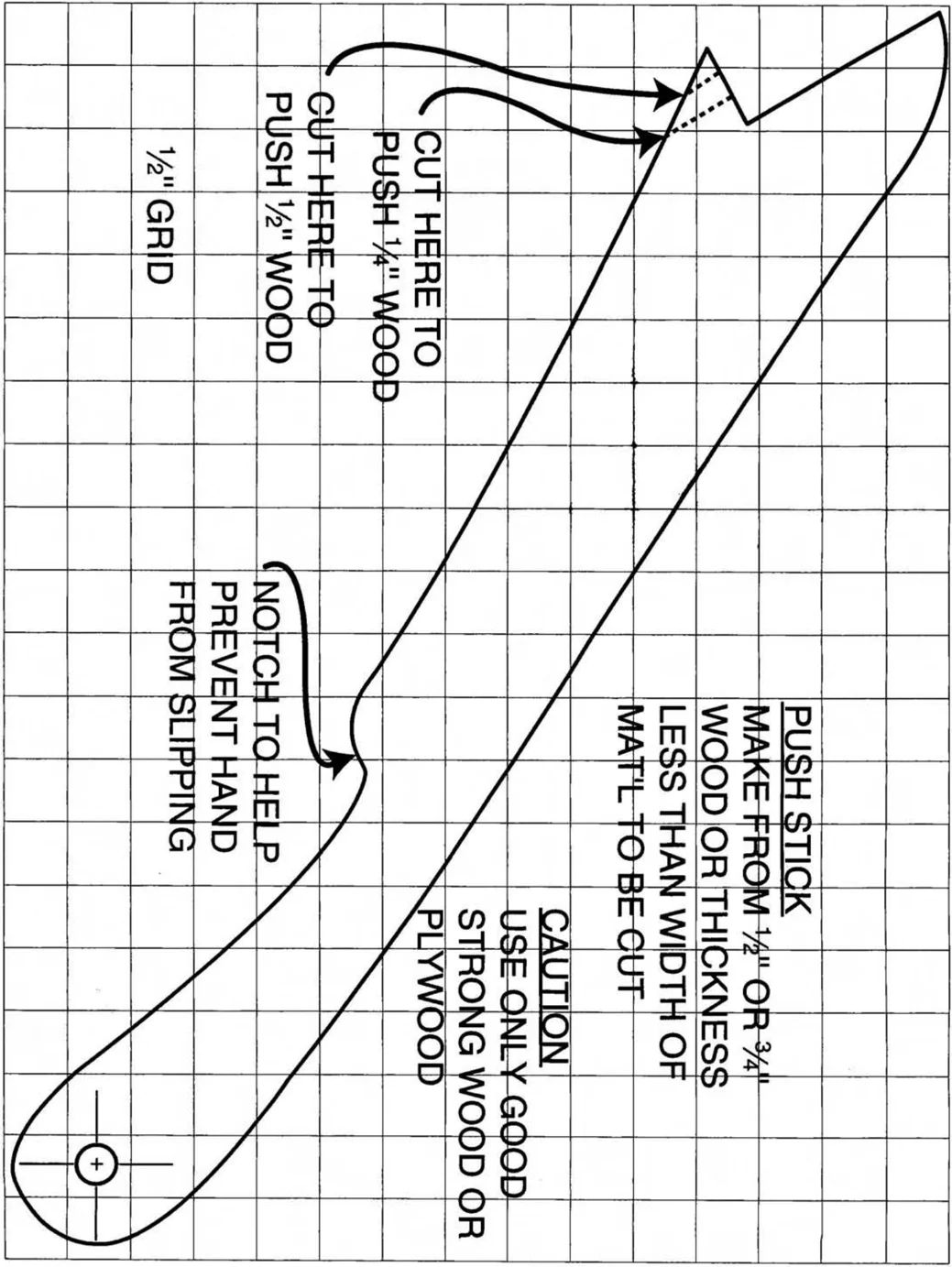
PUSH STICK MAKE FROM 1/2" OR 3/4" WOOD OR THICKNESS LESS THAN WIDTH OF MAT'L TO BE CUT
CAUTION USE ONLY GOOD STRONG WOOD OR PLYWOOD
CUT HERE TO PUSH 1/4" WOOD
CUT HERE TO PUSH 1/2" WOOD
NOTCH TO HELP PREVENT HAND FROM SLIPPING
1/2" GRID
14095017
Parts and Service Information
Grizzly stands behind its products with a full parts inventory. These parts are available for purchase by Grizzly machine owners regardless of whether you are the original owner or a subsequent owner. If you are the original owner, please fill out the warranty information on the warranty card, remove the card from this manual and send it back to us within 10 days of product delivery. We appreciate any comments or suggestions and use them to better our products and service.
If you are not the original owner, please fill out one of the cards below, remove the card from the manual and send it back to us. By registering with us, you will have the same access to parts and service as the original owner.
If you need service or help with this machine, please call or write to us at the appropriate regional service location listed on page 1 of this manual.
CHANGE OF OWNERSHIP
Original Owner Machine name & model no. _________________________
Name __________________________________________ Phone Number _________________________
Street _________________________________________________________________
City ___________________________________________________________________
State ____________________ ZIP ____________________ Date purchased _________________________
New Owner
Name __________________________________________ Phone Number _________________________
Street _________________________________________________________________
City ___________________________________________________________________
State ____________________ ZIP ____________________ Date purchased _________________________
CHANGE OF OWNERSHIP
Original Owner Machine name & model no. _________________________
Name __________________________________________ Phone Number _________________________
Street _________________________________________________________________
City ___________________________________________________________________
State ____________________ ZIP ____________________ Date purchased _________________________
New Owner
Name __________________________________________ Phone Number _________________________
Street _________________________________________________________________
City ___________________________________________________________________
State ____________________ ZIP ____________________ Date purchased _________________________
This page is blank.