SECTION 2: POWER SUPPLY
Availability
Before installing the machine, consider the availability and proximity of the required power supply circuit. If an existing circuit does not meet the requirements for this machine, a new circuit must be installed. To minimize the risk of electrocution, fire, or equipment damage, installation work and electrical wiring must be done by an electrician or qualified service personnel in accordance with all applicable codes and standards.
 WARNING
Electrocution, fire, shock, or equipment damage may occur if machine is not properly grounded and connected to power supply.
Full-Load Current Rating
The full-load current rating is the amperage a machine draws at 100% of the rated output power. On machines with multiple motors, this is the amperage drawn by the largest motor or sum of all motors and electrical devices that might operate at one time during normal operations.
- Full-Load Current Rating at 240V ........ 15 Amps
The full-load current is not the maximum amount of amps that the machine will draw. If the machine is overloaded, it will draw additional amps beyond the full-load rating.
If the machine is overloaded for a sufficient length of time, damage, overheating, or fire may result—especially if connected to an undersized circuit. To reduce the risk of these hazards, avoid overloading the machine during operation and make sure it is connected to a power supply circuit that meets the specified circuit requirements.
Circuit Information
A power supply circuit includes all electrical equipment between the breaker box or fuse panel in the building and the machine. The power supply circuit used for this machine must be sized to safely handle the full-load current drawn from the machine for an extended period of time. (If this machine is connected to a circuit protected by fuses, use a time delay fuse marked D.)
CAUTION For your own safety and protection of property, consult an electrician if you are unsure about wiring practices or electrical codes in your area.
Note: Circuit requirements in this manual apply to a dedicated circuit—where only one machine will be running on the circuit at a time. If machine will be connected to a shared circuit where multiple machines may be running at the same time, consult an electrician or qualified service personnel to ensure circuit is properly sized for safe operation.
Circuit Requirements
This machine is prewired to operate on a power supply circuit that has a verified ground and meets the following requirements:
- Nominal Voltage ........ 208V, 220V, 230V, 240V
- Cycle ........ 60 Hz
- Phase ........ Single-Phase
- Power Supply Circuit ........ 20 Amps
- Plug/Receptacle ........ NEMA 6-20
-12- Model G0490/G0490X (Mfd. Since 8/12)
Grounding Requirements
This machine MUST be grounded. In the event of certain malfunctions or breakdowns, grounding reduces the risk of electric shock by providing a path of least resistance for electric current.
This machine is equipped with a power cord that has an equipment-grounding wire and a grounding plug. Only insert plug into a matching receptacle (outlet) that is properly installed and grounded in accordance with all local codes and ordinances. DO NOT modify the provided plug!

Figure 4. Typical 6-20 plug and receptacle.
CAUTION
No adapter should be used with plug. If plug does not fit available receptacle, or if machine must be reconnected for use on a different type of circuit, reconnection must be performed by an electrician or qualified service personnel, and it must comply with all local codes and ordinances.
WARNING
Serious injury could occur if you connect machine to power before completing setup process. DO NOT connect to power until instructed later in this manual.
Improper connection of the equipment-grounding wire can result in a risk of electric shock. The wire with green insulation (with or without yellow stripes) is the equipment-grounding wire. If repair or replacement of the power cord or plug is necessary, do not connect the equipment-grounding wire to a live (current carrying) terminal.
Check with a qualified electrician or service personnel if you do not understand these grounding requirements, or if you are in doubt about whether the tool is properly grounded. If you ever notice that a cord or plug is damaged or worn, disconnect it from power, and immediately replace it with a new one.
Extension Cords
We do not recommend using an extension cord with this machine. If you must use an extension cord, only use it if absolutely necessary and only on a temporary basis.
Extension cords cause voltage drop, which can damage electrical components and shorten motor life. Voltage drop increases as the extension cord size gets longer and the gauge size gets smaller (higher gauge numbers indicate smaller sizes).
Any extension cord used with this machine must be in good condition and contain a ground wire and matching plug/receptacle. Additionally, it must meet the following size requirements:
- Minimum Gauge Size ........ 12 AWG
- Maximum Length (Shorter is Better) ........ 50 ft.


SECTION 3: SETUP
Needed for Setup
The following are needed to complete the setup process:
| Description | Qty |
|---|---|
| Additional People | 1 |
| Safety Glasses | 1 Per Person |
| Cleaner/Degreaser (Page 16) | As Needed |
| Disposable Shop Rags | As Needed |
| Lifting Equipment (At Least 750 lb. Rating): | |
| —Forklift or Hoist | 1 |
| —Lifting Straps | 2 |
| Wrench or Socket 13mm | 1 |
| Wrenches or Sockets 17mm | 2 |
| Wrench or Socket 10mm | 1 |
| Straightedge 4' | 1 |
| Screwdriver Phillips #2 | 1 |
| Screwdriver Flat Head #2 | 1 |
| Dust Collection System | 1 |
| Dust Hose 4" | 1 |
| Hose Clamps 4" | 2 |
Unpacking
This machine was carefully packaged for safe transport. When unpacking, separate all enclosed items from packaging materials and inspect them for shipping damage. If items are damaged, please call us immediately at (570) 546-9663.
IMPORTANT: Save all packaging materials until you are completely satisfied with the machine and have resolved any issues between Grizzly or the shipping agent. You MUST have the original packaging to file a freight claim. It is also extremely helpful if you need to return your machine later.
-14- Model G0490/G0490X (Mfd. Since 8/12)


Inventory
The following is a list of items shipped with your machine. Before beginning setup, lay these items out and inventory them.
If any non-proprietary parts are missing (e.g. a nut or a washer), we will gladly replace them; or for the sake of expediency, replacements can be obtained at your local hardware store.
Inventory: (Figures 5–6)
| Qty | Item |
|---|---|
| 1 | A. Jointer Assembly |
| 1 | B. Fence Carriage |
| 1 | C. Fence |
| 1 | D. Cutterhead Guard |
| 1 | E. Fence Tilt Lever |
| 1 | F. General Tools: |
| —Wrench 8/10mm | |
| —Wrench 12/14mm | |
| —Hex Wrenches 2.5, 4, 5, 6, 8mm... 1 Each | |
| 2 | G. Push Blocks |
| 1 | H. Stand w/Motor |
| 1 | I. Control Panel Pedestal Assembly |
| 1 | J. Pedal Assembly |
| 1 | K. Belt Guard |
| 1 | L. Poly V-Belt 8PK-1172 |
| 1 | M. Dust Port |
Hardware Bag (Not Shown):
- Carriage Bolts M8-1.25 x 25 (Motor) ........ 2
- Flat Washers 8mm (Motor) ........ 2
- Hex Nuts M8-1.25 (Motor) ........ 2
- Hex Bolt M8-1.25 x 50 (Wheel/Stand) ........ 1
- Flat Washer 8mm (Wheel/Stand) ........ 1
- Hex Bolts M10-1.5 x 55 (Wheel/Stand) ........ 2
- Flat Washers 10mm (Wheel/Stand) ........ 2
- Hex Nuts M10-1.5 (Wheel/Stand) ........ 2
- Cap Screws M8-1.25 x 25 (Jointer/Stand) ........ 8
- Lock Washers 8mm (Jointer/Stand) ........ 8
- Cap Screws M10-1.5 x 25 (Pedestal) ........ 2
- Lock Washers 10mm (Pedestal) ........ 2
- Flange Bolts M6-1 x 10 (Belt Guard) ........ 2
- Flat Washers 6mm (Belt Guard) ........ 2
- Hex Nuts M6-1 (Belt Guard) ........ 2
G0490 Knife Setting Gauge (Not Shown):
- External Retaining Rings 8mm ........ 2
- Knife Gauge Feet ........ 2
- Knife Gauge Rod ........ 1
G0490X Cutterhead Hardware (Not Shown):
- Driver Bits Torx T20 ........ 2
- L-Wrenches Torx T20 ........ 2
- Flat Hd Torx Screws T20 M6-1 x 15 ........ 3
- Indexable Carbide Inserts 14 x 14 x 2mm .. 5

Figure 5. G0490/G0490X inventory—box 1.

Figure 6. G0490/G0490X inventory—box 2.
NOTICE
If you cannot find an item on this list, carefully check around/inside the machine and packaging materials. Often, these items get lost in packaging materials while unpacking or they are pre-installed at the factory.
Cleanup
The unpainted surfaces of your machine are coated with a heavy-duty rust preventative that prevents corrosion during shipment and storage. This rust preventative works extremely well, but it will take a little time to clean.
Be patient and do a thorough job cleaning your machine. The time you spend doing this now will give you a better appreciation for the proper care of your machine's unpainted surfaces.
There are many ways to remove this rust preventative, but the following steps work well in a wide variety of situations. Always follow the manufacturer's instructions with any cleaning product you use and make sure you work in a well-ventilated area to minimize exposure to toxic fumes.
Before cleaning, gather the following:
- Disposable rags
- Cleaner/degreaser (WD•40 works well)
- Safety glasses & disposable gloves
- Plastic paint scraper (optional)
Basic steps for removing rust preventative:
- Put on safety glasses.
- Coat the rust preventative with a liberal amount of cleaner/degreaser, then let it soak for 5–10 minutes.
- Wipe off the surfaces. If your cleaner/degreaser is effective, the rust preventative will wipe off easily. If you have a plastic paint scraper, scrape off as much as you can first, then wipe off the rest with the rag.
- Repeat Steps 2–3 as necessary until clean, then coat all unpainted surfaces with a quality metal protectant to prevent rust.
T23692—Orange Power Degreaser A great product for removing the waxy shipping grease from your machine during clean up.
Figure 7. T23692 Orange Power Degreaser.
-16- Model G0490/G0490X (Mfd. Since 8/12)


Site Considerations
Weight Load
Refer to the Machine Data Sheet for the weight of your machine. Make sure that the surface upon which the machine is placed will bear the weight of the machine, additional equipment that may be installed on the machine, and the heaviest workpiece that will be used. Additionally, consider the weight of the operator and any dynamic loading that may occur when operating the machine.
Space Allocation
Consider the largest size of workpiece that will be processed through this machine and provide enough space around the machine for adequate operator material handling or the installation of auxiliary equipment. With permanent installations, leave enough space around the machine to open or remove doors/covers as required by the maintenance and service described in this manual. See below for required space allocation.

Physical Environment
The physical environment where the machine is operated is important for safe operation and longevity of machine components. For best results, operate this machine in a dry environment that is free from excessive moisture, hazardous chemicals, airborne abrasives, or extreme conditions. Extreme conditions for this type of machinery are generally those where the ambient temperature range exceeds 41°–104°F; the relative humidity range exceeds 20%–95% (non-condensing); or the environment is subject to vibration, shocks, or bumps.
Electrical Installation
Place this machine near an existing power source. Make sure all power cords are protected from traffic, material handling, moisture, chemicals, or other hazards. Make sure to leave enough space around machine to disconnect power supply or apply a lockout/tagout device, if required.
Lighting
Lighting around the machine must be adequate enough that operations can be performed safely. Shadows, glare, or strobe effects that may distract or impede the operator must be eliminated.
 Figure 8. Minimum working clearances.

Assembly
To properly prepare your jointer for operation, complete all of the steps in the assembly procedure prior to performing the Test Run on Page 24.
To assemble your jointer:
-
With help of another person, tip stand shipping box upside down, then lift shipping box off stand.
-
Place a piece of cardboard on floor, tip stand over so stand top is on cardboard, then remove plastic from stand.
-
Reach inside stand and remove accessories box, poly V-belt, and dust port.
-
Unbolt control panel pedestal from inside stand and set it off to the side.
-
Remove rear stand panel.
-
Reach inside stand and remove the (2) M8-1.25 x 25 hex nuts and (2) 8mm flat washers that secure motor to cabinet top.
Note: Retain the two carriage bolts, hex nuts, and flat washers so that they can be used to install motor in a later step.
-
Using cardboard to protect stand and another person to hold motor, place the stand on its left side so that dust chute is face down on floor.
-
Place motor on the two motor mount brackets with pulley facing rear of stand, as shown in Figure 9.

Figure 9. Motor installed.
-
Attach motor to motor mount brackets with (4) M8-1.25 x 25 carriage bolts, (4) 8mm flat washers, and (4) M8-1.25 hex nuts (two sets from inventory and two sets that were removed in Step 6), as shown in Figure 9.
Note: Pulley alignment and V-belt installation will take place in later steps.
-
Attach pedal assembly to right side of stand with (1) M8-1.25 x 50 hex bolt, (2) M8-1.25 x 55 hex bolts, (3) 8mm flat washers, and (2) M8-1.25 hex nuts, as shown in Figure 10.

Figure 10. Installing the pedal assembly.
-18- Model G0490/G0490X (Mfd. Since 8/12)
-
From inside stand, insert power cord plug through the same hole in stand that control panel pedestal cord is in.
-
With help of another person, place stand upright.
-
Attach dust port to stand with pre-installed Phillips screws and flat washers, as shown in Figure 11.

Figure 11. Installing dust port.
-
Remove the (2) hex nuts and flat washers from underneath shipping crate that hold the jointer assembly to the crate.
-
Wrap lifting straps around infeed and outfeed table, as illustrated in Figure 12, then attach them to forklift forks or hoist.

Figure 12. Using lifting straps to lift jointer assembly.
- With another person to steady load, carefully lift jointer assembly over stand and align the eight mounting holes in stand with holes in bottom of jointer assembly.
Note: Make sure the cutterhead pulley is facing to the rear of the stand.
- Attach jointer assembly to the stand with (8) M8-1.25 x 25 cap screws and (8) 8mm lock washers, as shown in Figure 13.

Figure 13. Securing the jointer assembly to the stand.
- Attach control panel pedestal to back of the infeed table with (2) M10-1.5 x 25 cap screws and (2) 10mm lock washers, as shown in Figure 14.

Figure 14. Installing control panel pedestal.
- Visually check alignment of cutterhead and motor pulleys, as illustrated in Figure 15.
 Figure 15. Pulleys aligned.
—If they are not aligned, loosen the four mounting carriage bolts shown in Figure 16, shift motor horizontally to align pulleys, then retighten carriage bolts.
 Figure 16. Motor adjustment controls.
- Use the two pre-installed cap screws and flat washers to install fence carriage to rear of jointer assembly, as shown in Figure 17.
 Figure 17. Fence carriage installed.
- Wrap poly V-belt around cutterhead and motor pulleys, as shown in Figure 18. Make sure ribs of V-belt are seated in pulley grooves.
 Figure 18. Poly V-belt installed.
22. Loosen carriage bolts securing motor mounting brackets (see Figure 19), let motor slide down to tension V-belt, then retighten carriage bolts.

Figure 19. Motor mounting carriage bolts.
Note: When properly tensioned, there is approximately 1/4" deflection of V-belt as moderate pressure is applied midway between the pulleys, as illustrated in Figure 20. If necessary, apply downward pressure on motor to attain proper V-belt tension.

Figure 20. Correct V-belt deflection when properly tensioned.
23. Use the two pre-installed cap screws on fence carriage to install fence, as shown in Figure 21.

Figure 21. Installing fence.
24. Install fence tilt lever, as shown in Figure 22.

Figure 22. Installing fence tilt lever.
WARNING The outfeed table MUST be level with cutterhead knives or inserts when they are at top dead center (their highest point during rotation). Otherwise, the workpiece cannot properly feed past the cutterhead, which may cause a kickback hazard to the operator.
-
Place straightedge on outfeed table so it extends over cutterhead.
-
Use cutterhead pulley to rotate cutterhead until one of the knives or inserts is at top dead center (their highest point during rotation), as illustrated in Figures 23–24.
 Figure 23. Knife or insert at top dead center.
 Figure 24. Using straightedge to check outfeed table height.
When the outfeed table height is correctly set, the knife or insert at top dead center will barely touch the straightedge, as illustrated in Figure 24.
—If knife or insert lifts straightedge off table or is below straightedge, then outfeed table height must be reset (refer to Setting Outfeed Table Height on Page 43 for detailed instructions).
CAUTION Belt guard MUST be installed before operating jointer or else moving V-belt will be exposed, creating an entanglement hazard at back of jointer.
- Use (2) M6-1 x 10 flange bolts, (2) 8mm flat washers, and (2) M6-1 hex nuts to install belt guard underneath the fence carriage, as shown in Figure 25.
 Figure 25. Installing belt guard.
- Model G0490 Only: Assemble knife setting gauge, as shown in Figure 26.
 Figure 26. Knife setting gauge assembled.
29. Re-install rear stand panel.
30. Move fence back as far as you can to make room for cutterhead guard.
31. Insert cutterhead guard shaft into extension fence, as shown in Figure 27, so shaft flat is facing set screw, then tighten set screw against shaft.
 Figure 27. Installing cutterhead guard.
32. Test operation of guard by pulling it back and letting go. Guard should spring back over cutterhead.
—If guard drags across table, loosen set screw, raise guard slightly so that it does not drag, then retighten set screw.
—If the guard does not spring back over cutterhead, re-install it and make sure flat part of guard shaft faces set screw.
Dust Collection
CAUTION DO NOT operate Model G0490/G0490X without an adequate dust collection system. This jointer creates substantial amounts of wood dust while operating. Failure to use a dust collection system can result in short and long-term respiratory illness.
Recommended CFM at Dust Port: 400 CFM Do not confuse this CFM recommendation with the rating of the dust collector. To determine the CFM at the dust port, you must consider these variables: (1) CFM rating of the dust collector, (2) hose type and length between the dust collector and the machine, (3) number of branches or wyes, and (4) amount of other open lines throughout the system. Explaining how to calculate these variables is beyond the scope of this manual. Consult an expert or purchase a good dust collection "how-to" book.
To connect a dust collection hose:
- Fit 4" dust hose over dust port on left side of stand and secure in place with a hose clamp.
- Tug hose to make sure it does not come off.
Note: A tight fit is necessary for proper performance.
Test Run
Once assembly is complete, test run the machine to ensure it is properly connected to power and safety components are functioning correctly.
If you find an unusual problem during the test run, immediately stop the machine, disconnect it from power, and fix the problem BEFORE operating the machine again. The Troubleshooting table in the SERVICE section of this manual can help.
⚠WARNING
Serious injury or death can result from using this machine BEFORE understanding its controls and related safety information. DO NOT operate, or allow others to operate, machine until the information is understood.
⚠WARNING
DO NOT start machine until all preceding setup instructions have been performed. Operating an improperly set up machine may result in malfunction or unexpected results that can lead to serious injury, death, or machine/property damage.
To test run machine:
- Push STOP button in (see Figure 28).

Figure 28. STOP/START button locations.
- Connect machine to power source by inserting power cord plug into a matching receptacle.
- Twist STOP button clockwise until it pops out. This resets button so machine will start.
- Push START button to turn machine ON. A correctly operating machine runs smoothly with little or no vibration or rubbing noises.
- Press STOP button to turn machine OFF.
- WITHOUT resetting STOP button, press START button. Machine should not start.
—If machine does not start, the STOP button safety feature is working correctly. Congratulations! The Test Run is complete.
—If machine does start (with STOP button pushed in), immediately disconnect power to machine. The STOP button safety feature is not working correctly. This safety feature must work properly before proceeding with regular operations. Call Tech Support for help.
Recommended Adjustments
For your convenience, the adjustments listed below have been performed at the factory and no further setup is required to operate your machine. However, because of the many variables involved with shipping, we recommend that you at least verify the following adjustments to ensure the best possible results from your new machine.
Factory adjustments that should be verified:
- Model G0490 Knife Settings (refer to Page 37).
- Depth Scale Calibration (refer to Page 44).
- Fence Stop Accuracy (refer to Page 45).
- Table Parallelism (refer to Page 39).


SECTION 4: OPERATIONS
WARNING To reduce your risk of serious injury, read this entire manual BEFORE using machine.
WARNING Damage to your eyes, lungs, and ears could result from using this machine without proper protective gear. Always wear safety glasses, a respirator, and hearing protection when operating this machine.

WARNING Loose hair, clothing, or jewelry could get caught in machinery and cause serious personal injury. Keep these items away from moving parts at all times to reduce this risk.
NOTICE If you have never used this type of machine or equipment before, WE STRONGLY RECOMMEND that you read books, review industry trade magazines, or get formal training before beginning any projects. Regardless of the content in this section, Grizzly Industrial will not be held liable for accidents caused by lack of training.
Operation Overview
This overview covers the basic process that happens during a typical operation with this machine. Familiarize yourself with this process to better understand the controls and procedures explained throughout the Operations section.
To complete a typical operation with the jointer, the operator does the following:
- Examines workpiece to verify it is safe and suitable for cutting.
- Adjusts fence for width of workpiece and locks it in place.
- Adjusts fence tilt, if necessary.
- Adjusts infeed table height to set depth of cut per pass.
- Puts on safety glasses, respirator, and ear protection.
- Starts jointer.
- Using push blocks as needed, holds work-piece firmly against infeed table and fence, and slides it into cutterhead at a steady and controlled rate until entire length of workpiece has advanced beyond cutterhead to outfeed table.
- Repeats cutting process until desired results are achieved.
- Stops jointer.


Stock Inspection & Requirements
Follow these rules when choosing and jointing stock:
-
DO NOT joint or surface place stock that contains large or loose knots. Injury to the operator or damage to the workpiece can occur if a knot becomes dislodged during the cutting operation.
-
Jointing and surface planing with the grain is safer for the operator and produces a better finish. Cutting against the grain increases the likelihood of kickback and workpiece tear-out. DO NOT cut against the grain! Cutting with the grain is feeding the stock across the cutterhead so the grain points down and back, as viewed from the front edge of the stock (see Figure 29).
Note: If the grain changes direction along the edge of the workpiece, decrease the depth of cut and make additional passes.

Figure 29. Proper grain alignment with the cutterhead.
-
Only process natural wood fiber through your jointer. Your jointer is designed to cut only natural wood stock. This machine is NOT designed to cut metal, glass, stone, tile, products with lead-based paint, or products that contain asbestos—cutting these materials with a jointer may lead to injury.
-
Scrape all glue off the workpiece before jointing. Glue deposits on the workpiece, hard or soft, will gum up the cutterhead and produce poor results.
-
Remove foreign objects from the workpiece. Make sure that any stock you process with the jointer is clean and free of dirt, nails, staples, tiny rocks or any other foreign objects, that could damage the cutterhead. These particles could also cause a spark as they strike the cutterhead and create a fire hazard.
Note: Wood stacked on a concrete or dirt surface can have small pieces of concrete or stone pressed into the surface.
-
Make sure all stock is sufficiently dried before jointing. Wood with a moisture content over 20% will cause unnecessary wear on the cutters and poor cutting results. Excess moisture can also hasten rust and corrosion.
-
Make sure your workpiece exceeds the minimum dimension requirements, as shown in Figure 30, before processing it through the jointer, or the workpiece may break or kickback during the operation.

Figure 30. Minimum stock dimensions for jointer.
Squaring Stock
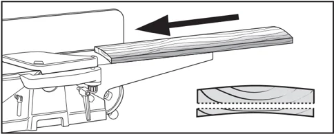
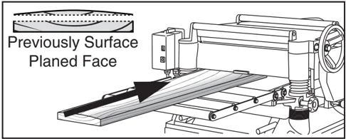
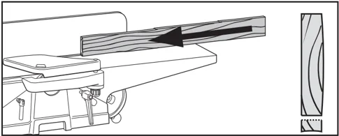
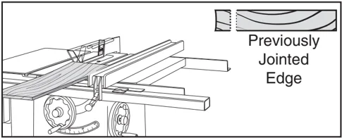
Squaring stock involves four steps performed in the order below:
-
Surface Plane on Jointer—Concave face of workpiece is surface planed flat with jointer.
-
Surface Plane on a Thickness Planer—Opposite face of workpiece is surface planed flat with a thickness planer. Previously Surface Planed Face
-
Edge Joint on Jointer—Concave edge of workpiece is jointed flat with jointer.
-
Rip Cut on a Table Saw—Jointed edge of workpiece is placed against a table saw fence and opposite edge cut off. Previously Jointed Edge
NOTICE
If you are not experienced with a jointer, set depth of cut to 0" and practice feeding workpiece across the tables as described for each of the jointing procedures. This process will better prepare you for actual operation.
Surface Planing
The purpose of surface planing (see Figures 31–32) on the jointer is to make one flat face on a piece of stock to prepare it for thickness planing on a planer.
 Figure 31. Example of surface planing operations.
 Removed Surface
Figure 32. Illustration of surface planing results.
To surface plane on jointer:
- Inspect stock to ensure it is safe and suitable for the operation (see Stock Inspection & Requirements section).
- Set infeed table height to desired cutting depth for each pass.
IMPORTANT: To minimize risk of kickback, do not exceed a cutting depth of 1/16" per pass when surface planing.
- Set fence to 90°.
- Start jointer.
- Place workpiece firmly against fence and infeed table.
IMPORTANT: To ensure workpiece remains stable during cut, concave sides of workpiece must face toward table and fence.
- Feed workpiece completely across cutterhead while keeping it firmly against fence and tables during the entire cut.
IMPORTANT: Keep hands at least 4" away from cutterhead during the entire cut. Instead of allowing a hand to pass directly over cutterhead, lift it up and over cutterhead, and safely reposition it on the outfeed side to continue supporting workpiece. Use push blocks whenever practical to further reduce risk of accidental hand contact with cutterhead.
- Repeat Step 6 until entire surface is flat.
Tip: When squaring up stock, cut opposite side of workpiece with a planer instead of the jointer to ensure boths sides are parallel.
!WARNING Failure to use push blocks when surface planing could result in your hands contacting rotating cutterhead, which will cause serious personal injury. ALWAYS use push blocks when surface planing on jointer!
-28- Model G0490/G0490X (Mfd. Since 8/12)

Edge Jointing
Edge jointing (see Figures 33–34 produces a flat and true surface along the side of a workpiece by removing uneven areas. It is an essential step for squaring up warped or rough stock and when preparing a workpiece for joinery or finishing.

Figure 33. Example of edge jointing operation.

Figure 34. Illustration of edge jointing results.
To edge joint on jointer:
-
Inspect stock to ensure it is safe and suitable for the operation (see Stock Inspection & Requirements section).
-
Set infeed table height to desired cutting depth for each pass.
IMPORTANT: To minimize risk of kickback, do not exceed a cutting depth of 1/8" per pass.
-
Set fence to 90°.
-
Start jointer.
-
Place workpiece firmly against fence and infeed table.
IMPORTANT: To ensure workpiece remains stable during cut, concave sides of workpiece must face toward table and fence.
-
Feed workpiece completely across cutterhead while keeping it firmly against fence and tables during the entire cut.
IMPORTANT: Keep hands at least 4" away from cutterhead during the entire cut. Instead of allowing a hand to pass directly over cutterhead, lift it up and over cutterhead, and safely reposition it on the outfeed side to continue supporting workpiece. Use push blocks whenever practical to further reduce risk of accidental hand contact with cutterhead.
-
Repeat Step 6 until the entire edge is flat.
Tip: When squaring up stock, cut opposite edge of workpiece with a table saw instead of the jointer—otherwise, both edges of workpiece will not be parallel with each other.
Bevel Cutting
Bevel cuts (see Figures 35–36) can be made by setting the fence at the desired angle and feeding the workpiece firmly along the fence face, with the bottom inside corner firmly against the table. The cutting process typically requires multiple passes or cuts to bevel the entire edge of a workpiece.

Figure 35. Fence setup for a bevel cut of 45°.

Figure 36. Illustration of bevel cutting results.
To bevel cut on jointer:
- Inspect stock to ensure it is safe and suitable for the operation (see Stock Inspection & Requirements section).
- Set infeed table height to cutting depth desired for each pass.
IMPORTANT: Cutting depth for bevel cuts is typically between 1/16" and 1/8", depending on hardness and width of stock.
- Set fence tilt to desired angle of cut.
- Place workpiece against fence and infeed table with concave side face down.
- Start jointer.
- With a push block in your leading hand, press workpiece against table and fence with firm pressure, and feed workpiece over cutterhead with a push block in your trailing hand.
Note: When your leading hand gets within 4" of the cutterhead, lift it up and over cutterhead, and place push block on portion of the workpiece once it is 4" past cutterhead. Now, focus your pressure on outfeed end of the workpiece while feeding, and repeat same action with your trailing hand when it gets within 4" of cutterhead. To help keep your hands safe, DO NOT let them get closer than 4" from moving cutterhead at any time during operation!
- Repeat cutting process, as necessary, until you are satisfied with the results.
Rabbet Cutting
The purpose of rabbet cutting (see Figures 37–38) is to remove a section of the workpiece edge, as shown below. When combined with another rabbet cut edge, the rabbet joints create a simple, yet strong method of joining stock.
 Figure 37. Typical rabbet cutting operation.
 Figure 38. Illustration of rabbet cutting effects and a few sample joints.
To rabbet cut on jointer:
-
Inspect stock to ensure it is safe and suitable for the operation (see Stock Inspection & Requirements section).
-
Set infeed table height to desired cutting depth for each pass.
IMPORTANT: For safety reasons, cutting depth should never exceed 1/8" per pass.
-
Remove cutterhead guard.
-
Set fence to 90° and near front of jointer, so amount of exposed cutterhead in front of fence matches size of desired rabbet.
-
Start jointer.
-
Place workpiece firmly against fence and infeed table.
IMPORTANT: To ensure workpiece remains stable during cut, concave sides of workpiece must face toward table and fence.
-
Feed workpiece completely across cutterhead while keeping it firmly against fence and tables during entire cut.
IMPORTANT: Keep hands at least 4" away from cutterhead during the entire cut. Instead of allowing a hand to pass directly over cutterhead, lift it up and over cutterhead, and safely reposition it on the outfeed side to continue supporting workpiece. Use push blocks whenever practical to further reduce risk of accidental hand contact with cutterhead.
-
Repeat Step 7 until rabbet is cut to depth.
!WARNING When cutterhead guard is removed, attempting any other cut besides a rabbet directly exposes operator to moving cutterhead. ALWAYS replace cutterhead guard after rabbet cutting!